
 Ask an Engineer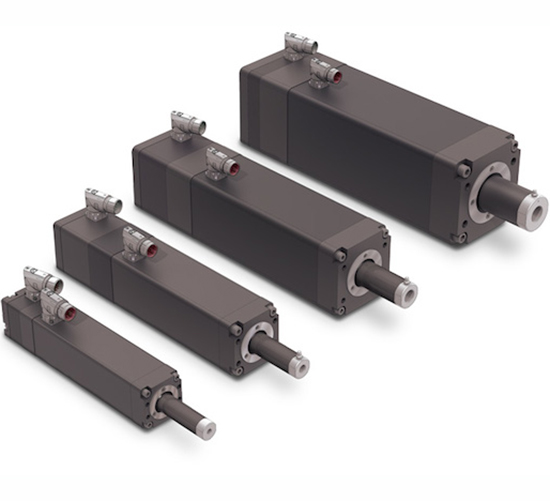
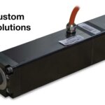
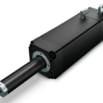
IMA Linear Servo Actuators
The IMA linear servo actuator includes an integrated servo motor to simplify mechanical designs
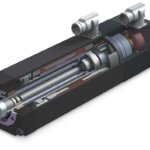
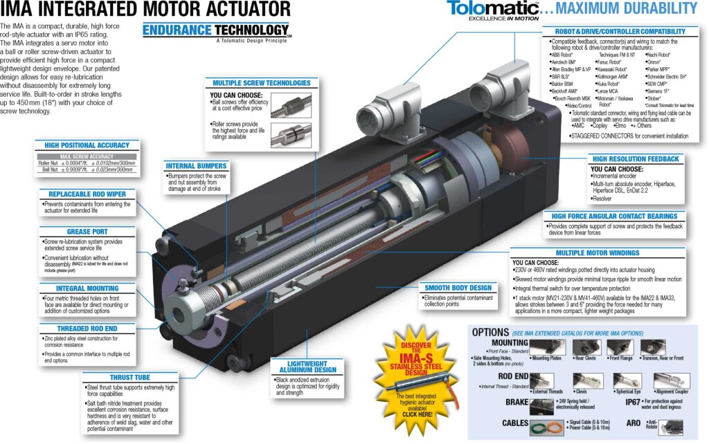
The IMA linear servo actuator features a unique integrated servo motor design in a compact, industrial package, that removes the need to source and attach a separate servo motor to the system. Ideal for hydraulic replacement, tight spaces, or when the actuator is exposed to a high level of shock and vibration.
- 4 body sizes with built-to-order stroke lengths and mounting options
- Stroke lengths up to 18 inches (457 mm)
- Forces up to 8,000 lbf (35.8 kN)
- Ball and Roller Screw options
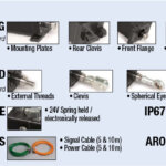
- IP67 option to protect against dust and water ingress
Find the right drive and cable connection to complete your system
Features & Ordering
Download the IMA Brochure for full details on features
IMA Features
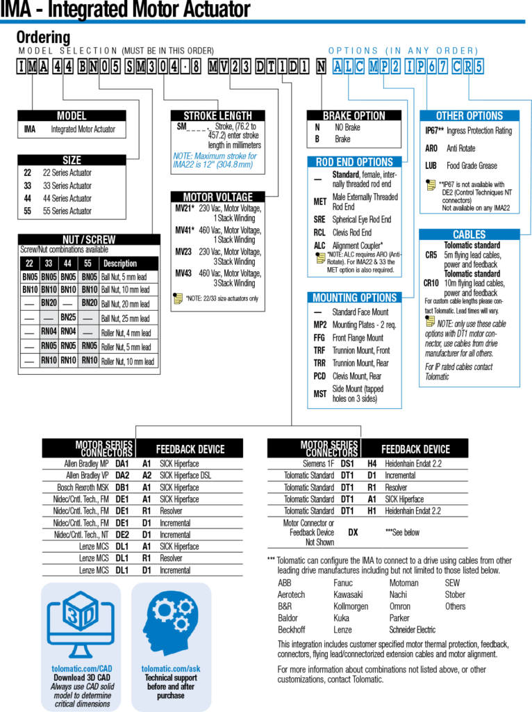
IMA Ordering
Specifications
| Specifications | Units | IMA22 | IMA33 | IMA44 | IMA55 |
|---|---|---|---|---|---|
| Maximum Stroke | in (mm) | 12 (305) | 18 (457) | 18 (457) | 18 (457) |
| Maximum Force | lbf (kN) | 325 (1.5) | 2,500 (11.1) | 4,150 (18.5) | 8,044 (35.8) |
| Maximum Speed | in/sec (mm/sec) | 28 (711) | 48 (1,219) | 52.5 (1,334) | 31.4 (787) |
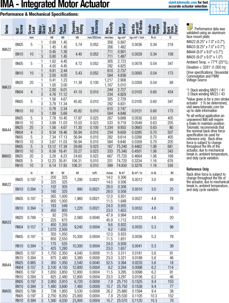
IMA Performance Specifications
IMA Motor Specifications
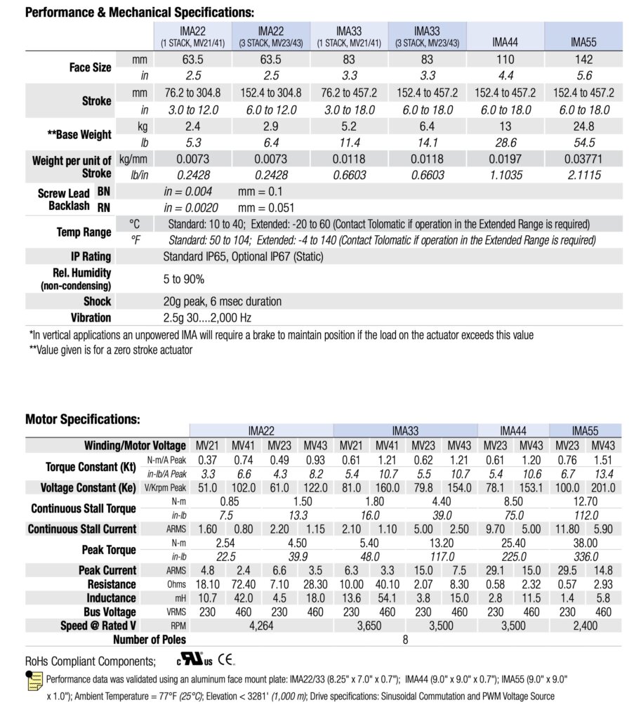
IMA Detailed Specifications
| IMA22 | IMA33 | IMA44 | IMA55 | ||||||||||
|---|---|---|---|---|---|---|---|---|---|---|---|---|---|
| Winding/Motor Voltage | MV21 | MV41 | MV23 | MV43 | MV21 | MV41 | MV23 | MV43 | MV23 | MV43 | MV23 | MV43 | |
| Torque Constant (K t ) | N-m/A Peak | 0.37 | 0.74 | 0.49 | 0.93 | 0.61 | 1.21 | 0.62 | 1.21 | 0.61 | 1.20 | 0.76 | 1.51 |
| in-lb/A Peak | 3.3 | 6.6 | 4.3 | 8.2 | 5.4 | 10.7 | 5.5 | 10.7 | 5.4 | 10.6 | 6.7 | 13.4 | |
| Voltage Constant (K e ) | V/Krpm Peak | 51 | 102 | 61 | 122 | 81 | 160 | 79.8 | 154 | 78.1 | 153.1 | 100 | 201 |
| Continuous Stall Torque | N-m | 0.85 | 0.85 | 1.50 | 1.50 | 1.8 | 1.8 | 4.4 | 4.3 | 8.4 | 8.5 | 12.7 | 12.7 |
| in-lb | 7.5 | 7.5 | 13.3 | 13.3 | 16 | 16 | 39 | 38 | 74 | 75 | 112 | 112 | |
| Continuous Stall Current | A RMS | 1.6 | 0.8 | 2.2 | 1.15 | 2.1 | 1.1 | 5 | 2.5 | 9.7 | 5 | 11.8 | 5.9 |
| Peak Torque | N-m | 2.54 | 2.54 | 4.5 | 4.5 | 5.4 | 5.4 | 13.2 | 12.9 | 25.1 | 25.4 | 38 | 38 |
| in-lb | 22.5 | 22.5 | 39.9 | 39.9 | 48 | 48 | 117 | 114 | 222 | 225 | 336 | 336 | |
| Peak Current | A RMS | 4.8 | 2.4 | 6.6 | 3.45 | 6.3 | 3.3 | 15 | 7.5 | 29.1 | 15 | 29.5 | 14.8 |
| Resistance | Ohms | 18.1 | 72.4 | 7.1 | 28.3 | 10 | 40.1 | 2.07 | 8.3 | 0.58 | 2.32 | 0.57 | 2.93 |
| Inductance | mH | 10.7 | 42 | 4.5 | 18 | 13.6 | 54.1 | 3.8 | 15 | 2.75 | 11.5 | 1.4 | 5.8 |
| Bus Voltage | V RMS | 230 | 460 | 230 | 460 | 230 | 460 | 230 | 460 | 230 | 460 | 230 | 460 |
| Speed @ Rated V | RPM | 4,264 | 3,650 | 3,500 | 3,500 | 2,400 | |||||||
| No. of Poles | 8 | ||||||||||||
RoHs Compliant Components;
Performance data was validated using an aluminum face mount plate: IMA22/33 (8.25″ x 7.0″ x 0.7″); IMA44 (9.0″ x 9.0″ x 0.7″); IMA55 (9.0″ x 9.0″ x 1.0″);
Ambient Temperature = 77°F (25°C); Elevation < 3281′ (1,000 m); Drive specifications: Sinusoidal Commutation and PWM Voltage Source
|
IMA22
(1 Stack, MV21/41)
|
IMA22
(3 Stack, MV23/43)
|
IMA33
(1 Stack, MV21/41)
|
IMA33
(3 Stack, MV23/43)
|
IMA44 | IMA55 | |||
|---|---|---|---|---|---|---|---|---|
| Face Size | mm | 63.5 | 63.5 | 83 | 83 | 110 | 142 | |
| in | 2.5 | 2.5 | 3.3 | 3.3 | 4.4 | 5.6 | ||
| Stroke | mm | 76.2 to 304.8 | 152.4 to 304.8 | 76.2 to 457.2 | 152.4 to 457.2 | 152.4 to 457.2 | 152.4 to 457.2 | |
| in | 3.0 to 12.0 | 6.0 to 12.0 | 3.0 to 18.0 | 6.0 to 18.0 | 6.0 to 18.0 | 6.0 to 18.0 | ||
| **Base Weight | kg | 2.4 | 2.9 | 5.2 | 6.4 | 13 | 24.8 | |
| lb | 5.3 | 6.4 | 11.4 | 14.1 | 28.6 | 54.5 | ||
| Weight per unit of stroke | kg/mm | 0.0073 | 0.0073 | 0.0118 | 0.0118 | 0.0197 | 0.03771 | |
| lb/in | 0.2428 | 0.2428 | 0.6603 | 0.6603 | 1.1035 | 2.1115 | ||
| Screw Lead Accuracy | BN | in/ft = 0.002 mm/300 = 0.051 (0.004 in/ft for IMA33BN20 and IMA44BN25) | ||||||
| RN | in/ft = 0.0004 mm/300 = 0.010 | |||||||
| Screw Lead Backlash | BN | in = 0.004 mm = 0.1 | ||||||
| RN | in = 0.0020 mm = 0.051 | |||||||
| Temp range | °C | Standard: 10 to 40; Extended: -20 to 60 (Contact Tolomatic if operation in the Extended Range is required) | ||||||
| °F | Standard: 50 to 104; Extended: -4 to 140 (Contact Tolomatic if operation in the Extended Range is required) | |||||||
| IP rating | Standard IP65, Optional IP67 (Static) | |||||||
| Rel. Humidity (non-condensing) | 5 to 90% | |||||||
| Shock | 20g peak, 6 msec duration | |||||||
| Vibration | 2.5g 30….2,000 Hz | |||||||
|
*In vertical applications an unpowered IMA will require a brake to maintain position if the load on the actuator exceeds this value
**Value given is for a zero stroke actuator
|
||||||||
| Series | Nut/Screw | Screw Lead | Motor Stack 1 | Cont. Thrust | Peak Thrust | Dynamic Load Rating | Lead Accuracy | Max. Velocity | Base Inertia 2 | Inertia per unit of Stroke | Break-away Torque | Nominal Back Drive Force 3 |
|---|---|---|---|---|---|---|---|---|---|---|---|---|
| in | lbf | lbf | lbf | in/ft | in/sec | lb-in2 | lb-in2 / in | in-lb | lbf | |||
| IMA22 | BN05 | 0.197 | 1 | 200 | 325 | 1,290 | 0.0021 | 14.0 | 0.306 | 0.0012 | 3.0 | 49 |
| 3 | 325 | 325 | 14.0 | 0.506 | ||||||||
| BN10 | 0.394 | 1 | 102 | 305 | 990 | 0.0021 | 28.0 | 0.308 | 0.0010 | 3.0 | 25 | |
| 3 | 180 | 325 | 28.0 | 0.508 | ||||||||
| IMA33 | BN05 | 0.197 | 1 | 365 | 1,000 | 1,960 | 0.0021 | 12.0 | 0.931 | 0.0027 | 4.8 | 78 |
| 3 | 900 | 1,000 | 11.5 | 1.649 | ||||||||
| BN10 | 0.394 | 1 | 183 | 549 | 1,220 | 0.0021 | 24.0 | 0.935 | 0.0032 | 4.8 | 39 | |
| 3 | 450 | 900 | 23.0 | 1.653 | ||||||||
| BN20 | 0.788 | 1 | 92 | 276 | 2,560 | 0.0040 | 47.9 | 0.994 | 0.0123 | 4.8 | 20 | |
| 3 | 225 | 675 | 45.9 | 1.712 | ||||||||
| RN04 | 0.157 | 1 | 450 | 1,350 | 9,240 | 0.0004 | 9.6 | 0.932 | 0.0035 | 5.3 | 98 | |
| 3 | 1,070 | 2,500 | 9.2 | 1.650 | ||||||||
| RN05 | 0.197 | 1 | 350 | 1,050 | 10,300 | 0.0004 | 12.0 | 0.933 | 0.0036 | 5.3 | 78 | |
| 3 | 850 | 2,550 | 11.5 | 1.651 | ||||||||
| RN10 | 0.394 | 1 | 175 | 525 | 10,300 | 0.0004 | 24.0 | 0.939 | 0.0041 | 5.3 | 39 | |
| 3 | 425 | 1,280 | 23.0 | 1.657 | ||||||||
| IMA44 | BN05 | 0.197 | 3 | 1,750 | 2,350 | 4,040 | 0.0009 | 11.5 | 3.311 | 0.0181 | 5.6 | 91 |
| BN10 | 0.394 | 3 | 875 | 2,480 | 3,380 | 0.0009 | 23.0 | 3.321 | 0.0188 | 5.6 | 46 | |
| BN25 | 0.985 | 3 | 350 | 1,050 | 2,540 | 0.0040 | 52.5 | 3.394 | 0.0233 | 5.6 | 18 | |
| RN04 | 0.157 | 3 | 2,100 | 4,150 | 12,800 | 0.0004 | 9.2 | 3.284 | 0.0098 | 6.2 | 114 | |
| RN05 | 0.197 | 3 | 1,650 | 3,850 | 12,800 | 0.0004 | 11.5 | 3.285 | 0.0098 | 6.2 | 91 | |
| RN10 | 0.394 | 3 | 825 | 2,480 | 12,800 | 0.0004 | 23.0 | 3.297 | 0.0106 | 6.2 | 46 | |
| IMA55 | BN05 | 0.197 | 3 | 2,950 | 3,910 | 6,720 | 0.0009 | 7.9 | 25.710 | 0.1525 | 9.4 | 153 |
| BN10 | 0.394 | 3 | 1,480 | 3,690 | 7,480 | 0.0009 | 15.7 | 25.750 | 0.1538 | 9.4 | 77 | |
| BN20 | 0.788 | 3 | 738 | 1,850 | 5,530 | 0.0009 | 26.2 | 25.880 | 0.1594 | 9.4 | 38 | |
| RN05 | 0.197 | 3 | 2,750 | 8,050 | 23,900 | 0.0004 | 7.9 | 25.530 | 0.1105 | 10.3 | 152 | |
| RN10 | 0.394 | 3 | 1,380 | 4,030 | 23,900 | 0.0004 | 15.7 | 25.570 | 0.1120 | 10.3 | 76 |
Performance data was validated using an aluminum face mount plate:
IMA22 (8.25″ x 7.0″ x 0.7″);
IMA33 (8.25″ x 7.0″ x 0.7″);
IMA44 (9.0″ x 9.0″ x 0.7″);
IMA55 (9.0″ x 9.0″ x 1.0″)
Ambient Temp. = 77°F (25°C);
Elevation < 3281′ (1,000 m);
Drive specifications: Sinusoidal Commutation and PWM Voltage Source
1 1 Stack winding MV21 / 41 3 Stack winding MV23 / 43
2 Value given is for a zero stroke actuator
† To be determined, visit www.tolomatic.com for up-to-date information
3 In all vertical application an unpowered IMA will require a brake to maintain position.
Tolomatic recommends that the nominal back drive force specification be used for reference only.
Back drive force is subject to change throughout the life of the actuator, due to mechanical break in, ambient temperature, and duty cycle variation.
| Series | Nut/Screw | Screw Lead | Motor Stack1 | Cont. Thrust | Peak Thrust | Dynamic Load Rating | Lead Accuracy | Max. Velocity | Base Inertia2 | Inertia per unit of Stroke | Break-away Torque | Nominal Back Drive Force3 |
|---|---|---|---|---|---|---|---|---|---|---|---|---|
| mm | kN | kN | kN | mm/300mm | mm/sec | kg-cm2 | kg-cm2 / mm | N-m | N | |||
| IMA22 | BN05 | 5 | 1 | 0.89 | 1.45 | 5.74 | 0.052 | 356 | 0.897 | 0.0036 | 0.34 | 218 |
| 3 | 1.45 | 1.45 | 356 | 1.482 | ||||||||
| BN10 | 10 | 1 | 0.45 | 1.36 | 4.40 | 0.052 | 711 | 0.901 | 0.0029 | 0.34 | 109 | |
| 3 | 0.80 | 1.45 | 711 | 1.487 | ||||||||
| IMA33 | BN05 | 5 | 1 | 1.62 | 4.45 | 8.72 | 0.052 | 305 | 2.723 | 0.0078 | 0.54 | 347 |
| 3 | 4.00 | 4.45 | 292 | 4.825 | ||||||||
| BN10 | 10 | 1 | 0.81 | 2.44 | 5.43 | 0.052 | 610 | 2.737 | 0.0093 | 0.54 | 173 | |
| 3 | 2.00 | 4.00 | 584 | 4.838 | ||||||||
| BN20 | 20 | 1 | 0.41 | 1.23 | 11.39 | 0.100 | 1,217 | 2.908 | 0.0359 | 0.54 | 89 | |
| 3 | 1.00 | 3.00 | 1,167 | 5.010 | ||||||||
| RN04 | 4 | 1 | 2.00 | 6.01 | 41.10 | 0.010 | 244 | 2.727 | 0.0103 | 0.60 | 434 | |
| 3 | 4.76 | 11.12 | 234 | 4.829 | ||||||||
| RN05 | 5 | 1 | 1.56 | 4.67 | 45.82 | 0.010 | 305 | 2.729 | 0.0105 | 0.60 | 347 | |
| 3 | 3.78 | 11.34 | 292 | 4.831 | ||||||||
| RN10 | 10 | 1 | 0.78 | 2.34 | 45.82 | 0.010 | 610 | 2.747 | 0.0121 | 0.60 | 173 | |
| 3 | 1.89 | 5.69 | 584 | 4.848 | ||||||||
| IMA44 | BN05 | 5 | 3 | 7.78 | 10.45 | 17.97 | 0.023 | 267 | 9.689 | 0.0530 | 0.63 | 405 |
| BN10 | 10 | 3 | 3.89 | 11.03 | 15.03 | 0.023 | 533 | 9.719 | 0.0549 | 0.63 | 205 | |
| BN25 | 25 | 3 | 1.56 | 4.67 | 11.30 | 0.100 | 1,334 | 9.933 | 0.0683 | 0.63 | 80 | |
| RN04 | 4 | 3 | 9.34 | 18.46 | 56.94 | 0.010 | 234 | 9.609 | 0.0285 | 0.70 | 507 | |
| RN05 | 5 | 3 | 7.34 | 17.13 | 56.94 | 0.010 | 292 | 9.614 | 0.0288 | 0.70 | 405 | |
| RN10 | 10 | 3 | 3.67 | 11.03 | 56.94 | 0.010 | 584 | 9.648 | 0.0309 | 0.70 | 205 | |
| IMA55 | BN05 | 5 | 3 | 13.12 | 17.39 | 29.89 | 0.023 | 167 | 75.240 | 0.4462 | 1.06 | 681 |
| BN10 | 10 | 3 | 6.58 | 16.41 | 33.27 | 0.023 | 333 | 75.340 | 0.4501 | 1.06 | 343 | |
| BN20 | 20 | 3 | 3.28 | 8.23 | 24.60 | 0.023 | 667 | 75.720 | 0.4664 | 1.06 | 169 | |
| RN05 | 5 | 3 | 12.23 | 35.81 | 106.31 | 0.010 | 201 | 74.720 | 0.3234 | 1.16 | 676 | |
| RN10 | 10 | 3 | 6.14 | 17.93 | 106.31 | 0.010 | 399 | 74.830 | 0.3279 | 1.16 | 338 |
Performance data was validated using an aluminum face mount plate:
IMA22 (8.25″ x 7.0″ x 0.7″);
IMA33 (8.25″ x 7.0″ x 0.7″);
IMA44 (9.0″ x 9.0″ x 0.7″);
IMA55 (9.0″ x 9.0″ x 1.0″)
Ambient Temp. = 77°F (25°C);
Elevation < 3281′ (1,000 m);
Drive specifications: Sinusoidal Commutation and PWM Voltage Source
1 1 Stack winding MV21 / 41 3 Stack winding MV23 / 43
2 Value given is for a zero stroke actuator
† To be determined, visit www.tolomatic.com for up-to-date information
3 In all vertical application an unpowered IMA will require a brake to maintain position.
Tolomatic recommends that the nominal back drive force specification be used for reference only.
Back drive force is subject to change throughout the life of the actuator, due to mechanical break in, ambient temperature, and duty cycle variation.
Dimensions
IMA Dimensions

Get CAD
Manuals & Part Sheets
Additional Resources
Information Center:
Application Checklists
- Electric Rod-Style Actuator Application Checklist
- _HOJA DE TRABAJO - DATOS DE APLICACIÓN (Electric Rod-Style Actuator Application Checklist-Spanish Translation)
- _FICHE TECHNIQUE DES DONNÉES D'APPLICATION (Electric Rod-Style Actuator Application Checklist-French Translation)
- _FOGLIO DI LAVORO - DATI APPLICATVI (Electric Rod-Style Actuator Application Checklist-Italian Translation)
- Anwendungsdatenarbeitsblatt (Electric Rod-Style Actuator Application Checklist-German)
- Hydraulic Cylinder Replacement Worksheet
Catalogs & Brochures
- Corporate Overview-Linear Motion Solutions Brochure (English)
- SOLUCIONES DE CONTROL DE MOVIMIENTO (Spanish, Corporate Overview-Motion Control Solutions Brochure)
- Unternehmensübersicht (German, Corporate Overview brochure)
- 汽车行业应用手册 Brochure (Chinese: Automotive Applications Brochure)
- Brochure sur l'entreprise Tolomatic (French, Corporate Overview-Linear Motion Solutions Brochure)
- IMA Integrated Servo Linear Actuator Catalog
- IMA with 2 & 4 Stack Motors
- IMA Actuador de vastago con motor integrado (IMA integrated actuator, ES)
- IMA ACTUADORES Opciones extendidas del catálogo (^ES IMA extended catalog)
- IMA Integrierter Servoantrieb Broschüre (IMA Actuator brochure, German)
- Automotive Applications Brochure
- Medical and Life Sciences brochure
- Electric Pressing Solutions Brochure
- IMA Antriebe Mit 2- Und 4-stufigen Motoren Für Maximale Dauerkraft (IMA-Extended Catalog ^DE)
Certifications
E-Books
Flyers
Guides
- Selecting the Optimal Screw Technology
- Actuator Life: How to estimate for ball and roller screw actuators
- INFOGRAPHIC: Accuracy and Repeatability in Linear Actuators
- INFOGRAPHIC: Calculating Total Cost of Ownership
- INFOGRAPHIC: Ten Tips for Specifying Electric Rod Actuators
- INFOGRAPHIC: Electric vs. Servo-hydraulic vs. Hydraulic Actuators
- 如何选择 螺杆? 甄选 正确的技术 (Chinese, How to select the right lead screw for an electric actuator)
- A Guide to Converting Hydraulics to Electric Actuators
- Abschnitt: Welches Gewinde? Die richtige Technologie auswählen (German - Which Screw)
- Guía para Conversión de Actuadores Hidráulicos a Eléctricos
Software & Firmware
Tech Bulletins
Terms & Conditions
Videos
White Papers
- Top Ten Tips: How to specify electric rod-style actuators for optimal performance, reliability and efficiency
- Electric actuators vs. pneumatic cylinders: A comparison based on total cost of ownership
- Select the right linear actuator: Making sense of manufacturer specifications
- Comparing traditional and integrated rod-style linear actuators: How to choose the best solution for motion control applications
- Rules of actuator and guide alignment in linear motion systems
- IP ratings and the manufacturing environment: How to apply linear actuators for quality, safety and long service life.
- Minimizing electrical noise in actuator drive systems for maximum reliability and performance
- Introduction to accuracy and repeatability in linear motion systems
- Evaluating actuators for washdown in food & beverage applications
- Electric Rod Actuators vs. Hydraulic Cylinders: A Comparison
- Elektrische Stangenantriebe vs. Hydraulikzylinder: Ein Vergleich der Vor- und Nachteile beider Technologien weißes Papier (Electric vs Hydraulic WP, German)
- A technical comparison: Performance of pneumatic cylinders and electric rod actuators
- Electric actuator technology comparison: Integrated and traditional designs
- How roller-screw and ball-screw actuators compare in high-force applications
- Actuadores eléctricos con vástago frente a cilindros hidráulicos: una comparación de los pros y los contras de cada tecnología (Spanish - White paper - Electric vs Hydraulic Actuators)
- Designing Gantry and Multi-Axis Automation Systems
- Diez Consejos Óptimos: Cómo especificar los actuadores eléctricos de vástago para obtener rendimiento, confiabilidad y eficiencia óptimos
- Comparación de la tecnología de los actuadores eléctricos: Diseños integrados y tradicionales
- Medical Device Motion Design Considerations
- Integrierte und traditionelle Bauweisen Weißbuch (DE, Integrated and traditional designs WP)
- Unleashing the Capabilities of the Linear Servo Press in Manufacturing
- Liberar las Capacidades de la Servoprensa Lineal en la Fabricación
- Making the Jump to Electric
- How Integrated Linear Actuators Simplify Design and Elevate Performance
- TOP 10 TIPPS: So spezifizieren Sie elektrische Stellantriebe in StabformAktuatoren für optimale Leistung, Zuverlässigkeit und Effizienz (How2specify^DE)
- TOP 10 TIPPS: So spezifizieren Sie elektrische Stellantriebe in StabformAktuatoren für optimale Leistung, Zuverlässigkeit und Effizienz (How2specify^DE)
Success Stories
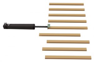
Challenge: A lumber processing equipment company needed to replace existing hydraulic cylinders used in a fencing application in order to achieve flexible positioning, reduce maintenance / contamination, and lower energy consumption.
Product Family: IMA
Product Used: IMA33
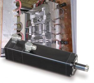
Challenge: An injection molding OEM was struggling with long lead times from their existing electric actuator supplier.
Product Family: IMA Integrated Motor Actuator
Product Used: IMA
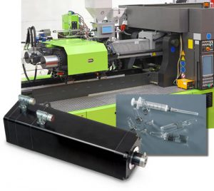
Challenge: Precise positioning of product, blowers, sealers, welders, and more.
Product Family: Electric
Product Used: IMA Integrated Motor Actuator
For injection molding and aseptic plastic equipment, hydraulic cylinders could meet force requirements but lacked the repeatability and accuracy needed for consistent part quality. Servo linear actuators addressed this gap by delivering tighter control over applied force and motion.
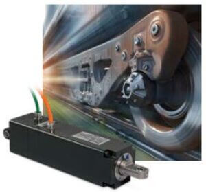
Application Description
An actuator to steer the wheels of a high-speed train car, to reduce the wear caused by curves in the track.
Product Used: Modified IMA44 Integrated Linear Servo Actuator
Product Type: Modified Standard
Unique application requirements play a significant role in selecting the appropriate servo linear actuator, Tolomatic offers several actuator families designed to address different operating conditions while maintaining the benefits of integrated servo control.
Additional IMA information
The IMA linear servo actuator features a unique integrated motor design in a compact, industrial package. Available in both ball and roller screw configurations, the IMA actuators provide forces up to 8,044 lbf (35.8 kN) ideal for high duty cycle applications.
Ideal for dynamic applications or when the actuator is exposed to a high level of shock and vibration.
Drive Integration
Tolomatic’s integrated motor products (IMA & IMAS) integrate with a wide range manufacturers’ servo drives. Check our Drive Integration Resource for supporting documentation and motor files.
Tolomatic supports integration with Rockwell Automation through the use of custom motor files (CMF). See our Tech Note: interfacing the IMA actuator and absolute encoder with Rockwell Automation servo drives.
Flexible design with options to fit your application
All machines are different. Tolomatic offers a variety of options to ensure compatibility and fit with your machine. Explore our catalogue of options and accessories.
Long service life with IMA linear servo actuators
Tolomatic’s patented re-lubrication design enables easy re-lubrication without disassembly for extremely long service life. Discover the options available.