
 Ask an Engineer
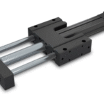
GSA Actuators
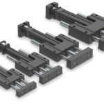
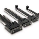
The GSA linear slide actuator is ideal for medium- to high-thrust applications.
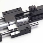
GSA Linear Slide Actuators combine an electric rod actuator with an integrated guide body, for compact applications where external guides can’t be used. The GSA offers high performance, dependability and mounting flexibility for high value applications.
- 4 Body Sizes
- Forces up to 4,160 lbf (18.5 kN)
- Stroke lengths up to 36 in (914 mm)
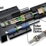
- Acme, Ball, and Roller Screw options
- Choice of linear ball or composite guide bearings
- Oversized guide rod options for high load situations
Features & Ordering
Download the GSA Brochure for full details on features
GSA-ST Features

GSA-HT Features

GSA Ordering

GSA Service Parts Ordering

Specifications
| Specifications | Units | GSA12 | GSA16 | GSA24 | GSA32 |
|---|---|---|---|---|---|
| Maximum Stroke | in (mm) | 18 (457) | 24 (609) | 30 (762) | 36 (914) |
| Maximum Force | lbf (N) | 130 (580) | 130 (580) | 1,700 (7,600) | 4,160 (18,500) |
| Maximum Load | lbs (kg) | 400 (182) | 500 (227) | 1,000 (454) | 1,200 (544) |
| Maximum Speed | in/sec (mm/sec) | 123 (3,124) | 123 (3,124) | 50 (1,270) | 50 (1,270) |
IMAGE-GSA-ST & HT Screw/Nut Specifications (US Standard)

IMAGE-GSA-ST & HT Screw/Nut Specifications (Metric)

GSA Detailed Specifications - US Measurements
| GSA SIZE | MAX. STROKE | SCREW TYPE | SCREW LEAD | MAX THRUST* | DYNAMIC LOAD RATING** | LEAD ACCURACY † | BACKLASH | Screw Diameter | BASE ACTUATOR INERTIA | INERTIA PER/in OF STROKE | MAXIMUM DYNAMIC FRICTION TORQUE | |
|---|---|---|---|---|---|---|---|---|---|---|---|---|
| LB | CB & COB | |||||||||||
| in | turns/in | lbf | lbf | in/ft | in | in | lb-in2 | lb-in2 | lb-in | lb-in | ||
| 12 | 18 | SN01 | 1.00 | 70 | NA | 0.010 | 0.007 | 0.375 | 0.044 | 0.006 | 2.9 | 5.6 |
| 18 | SN02 | 2.00 | 70 | NA | 0.006 | 0.007 | 0.375 | 0.013 | 0.002 | 1.5 | 2.8 | |
| 18 | SN05 | 5.00 | 70 | NA | 0.006 | 0.007 | 0.375 | 0.004 | 0.001 | 0.6 | 1.1 | |
| 18 | BZ10 | 10.00 | 70 | NA | 0.006 | 0.008 | 0.375 | 0.003 | 0.001 | 0.4 | 0.8 | |
| 18 | BN(L)08 | 8.00 | 130 | 300 | 0.003 | 0.015 | 0.375 | 0.003 | 0.001 | 0.5 | 0.7 | |
| 16 | 24 | SN01 | 1.00 | 70 | NA | 0.010 | 0.007 | 0.375 | 0.079 | 0.008 | 2.9 | 6.1 |
| 24 | SN02 | 2.00 | 70 | NA | 0.006 | 0.007 | 0.375 | 0.022 | 0.002 | 1.5 | 3.1 | |
| 24 | SN05 | 5.00 | 70 | NA | 0.006 | 0.007 | 0.375 | 0.006 | 0.001 | 0.6 | 1.3 | |
| 24 | BZ10 | 10.00 | 70 | NA | 0.006 | 0.008 | 0.375 | 0.004 | 0.001 | 0.4 | 0.9 | |
| 24 | BN(L)08 | 8.00 | 130 | 300 | 0.003 | 0.015 | 0.375 | 0.004 | 0.001 | 0.5 | 0.7 | |
| 24 | 30 | BZ10 | 10.00 | 600 | NA | 0.006 | 0.008 | 0.625 | 0.077 | 0.004 | 4.2 | 4.0 |
| 30 | BN(L)05 | 5.00 | 830 | 1,410 | 0.003 | 0.015 | 0.625 | 0.081 | 0.005 | 2.9 | 2.7 | |
| 30 | BN(L)02 | 2.00 | 340 | 1,070 | 0.003 | 0.015 | 0.500 | 0.115 | 0.006 | 2.9 | 2.7 | |
| 30 | BNM05 | 5.08 | 870 | 2,700 | 0.004 | 0.003 | 0.630 | 0.081 | 0.005 | 3.0 | 2.8 | |
| 30 | BNM10 | 2.54 | 430 | 1,910 | 0.004 | 0.003 | 0.630 | 0.100 | 0.006 | 3.0 | 2.8 | |
| 32 | 36 | BZ10 | 10.00 | 790 | NA | 0.006 | 0.008 | 0.750 | 0.126 | 0.009 | 5.5 | 6.1 |
| 36 | BN(L)05 | 5.00 | 950 | 1,620 | 0.003 | 0.015 | 0.750 | 0.135 | 0.010 | 4.2 | 4.8 | |
| 36 | BN(L)02 | 2.00 | 530 | 3,360 | 0.004 | 0.015 | 0.750 | 0.194 | 0.014 | 4.2 | 4.8 | |
| 36 | BNM05 | 5.08 | 1,360 | 3,080 | 0.004 | 0.003 | 0.787 | 0.134 | 0.012 | 4.4 | 5.0 | |
| 36 | BNM10 | 2.54 | 680 | 4,720 | 0.004 | 0.003 | 0.787 | 0.167 | 0.014 | 4.4 | 5.0 | |
| 36 | BNM20 | 1.27 | 340 | 2,560 | 0.002 | 0.005 | 0.787 | 0.299 | 0.025 | 4.4 | 5.0 | |
| 24 HT | 24 | RN04 | 6.35 | 1,700 | 5,580 | 0.0004 | 0.0012 | 0.591 | 0.09 | 0.037 | 6.3 | 6.1 |
| 24 | RN05 | 5.08 | 1,700 | 5,580 | 0.0004 | 0.0012 | 0.591 | 0.10 | 0.040 | 4.7 | 4.5 | |
| 24 | RN10 | 2.54 | 1,560 | 5,580 | 0.0004 | 0.0012 | 0.591 | 0.13 | 0.057 | 6.7 | 6.5 | |
| 32 HT | 36 | BZ10 | 10.00 | 2,500 | NA | 0.006 | 0.008 | 0.750 | 0.13 | 0.009 | 5.5 | 6.1 |
| 36 | BN(L)05 | 5.00 | 950 | 1,620 | 0.003 | 0.015 | 0.750 | 0.13 | 0.010 | 4.3 | 4.9 | |
| 36 | BN(L)02 | 2.00 | 2,500 | 3,360 | 0.004 | 0.015 | 0.750 | 0.19 | 0.014 | 4.3 | 4.9 | |
| 36 | BNM05 | 5.08 | 1,790 | 3,080 | 0.004 | 0.003 | 0.787 | 0.16 | 0.012 | 4.0 | 4.6 | |
| 36 | BNM10 | 2.54 | 2,470 | 4,720 | 0.004 | 0.003 | 0.787 | 0.22 | 0.015 | 4.0 | 4.6 | |
| 36 | BNM20 | 1.27 | 2,360 | 2,560 | 0.002 | 0.005 | 0.787 | 0.46 | 0.025 | 4.0 | 4.6 | |
| 36 | RN04 | 6.35 | 4,160 | 12,760 | 0.0004 | 0.0012 | 0.787 | 1.18 | 0.011 | 9.9 | 10.6 | |
| 36 | RN05 | 5.08 | 3,880 | 12,760 | 0.0004 | 0.0012 | 0.787 | 1.18 | 0.012 | 10.3 | 10.9 | |
| 36 | RN10 | 2.54 | 4,160 | 12,760 | 0.0004 | 0.0012 | 0.787 | 1.25 | 0.015 | 10.8 | 11.4 | |
Contact Tolomatic for higher accuracy and lower backlash options.
† (L) for low backlash ball screws: backlash = 0.0020” (0.05 mm)
* For SN & BZ screws, maximum continuous dynamic thrust subject to Thrust x Velocity limitation.
** For RN, BN & BNL screws, dynamic load rating reflects 90% reliability for 1 million revolutions.
GSA Detailed Specifications - Metric Measurements
| GSA SIZE | MAX. STROKE | SCREW TYPE | SCREW LEAD | MAX THRUST* | DYNAMIC LOAD RATING** | LEAD ACCURACY † | BACKLASH | Screw Diameter | BASE ACTUATOR INERTIA | INERTIA PER/in OF STROKE | MAXIMUM DYNAMIC FRICTION TORQUE | |
|---|---|---|---|---|---|---|---|---|---|---|---|---|
| LB | CB & COB | |||||||||||
| mm | mm/rev | N | N | mm/300 | mm | mm | kg-cm2 | kg-cm2 | N-m | N-m | ||
| 12 | 457.2 | SN01 | 25.40 | 310 | NA | 0.25 | 0.18 | 9.5 | 0.13 | 0.0006 | 0.33 | 0.64 |
| 457.2 | SN02 | 12.70 | 310 | NA | 0.15 | 0.18 | 9.5 | 0.04 | 0.0002 | 0.17 | 0.32 | |
| 457.2 | SN05 | 5.08 | 310 | NA | 0.15 | 0.18 | 9.5 | 0.01 | 0.0001 | 0.06 | 0.13 | |
| 457.2 | BZ10 | 2.54 | 310 | NA | 0.15 | 0.20 | 9.5 | 0.01 | 0.0001 | 0.05 | 0.09 | |
| 457.2 | BN(L)08 | 3.18 | 580 | 1,330 | 0.08 | 0.38 | 9.5 | 0.01 | 0.0001 | 0.06 | 0.08 | |
| 16 | 609.6 | SN01 | 25.40 | 310 | NA | 0.25 | 0.18 | 9.5 | 0.23 | 0.0009 | 0.33 | 0.69 |
| 609.6 | SN02 | 12.70 | 310 | NA | 0.15 | 0.18 | 9.5 | 0.06 | 0.0003 | 0.17 | 0.35 | |
| 609.6 | SN05 | 5.08 | 310 | NA | 0.15 | 0.18 | 9.5 | 0.02 | 0.0001 | 0.06 | 0.14 | |
| 609.6 | BZ10 | 2.54 | 310 | NA | 0.15 | 0.20 | 9.5 | 0.01 | 0.0001 | 0.05 | 0.11 | |
| 609.6 | BN(L)08 | 3.18 | 580 | 1,330 | 0.08 | 0.38 | 9.5 | 0.01 | 0.0001 | 0.06 | 0.08 | |
| 24 | 762.0 | BZ10 | 2.54 | 2,670 | NA | 0.08 | 0.38 | 15.9 | 0.22 | 0.0005 | 0.47 | 0.45 |
| 762.0 | BN(L)05 | 5.08 | 3,690 | 6,300 | 0.08 | 0.38 | 15.9 | 0.24 | 0.0005 | 0.33 | 0.31 | |
| 762.0 | BN(L)02 | 12.70 | 1,510 | 4,800 | 0.08 | 0.38 | 12.7 | 0.34 | 0.0007 | 0.33 | 0.31 | |
| 762.0 | BNM05 | 5.00 | 3,870 | 12,000 | 0.08 | 0.38 | 16.0 | 0.24 | 0.0006 | 0.34 | 0.32 | |
| 762.0 | BNM10 | 10.00 | 1,910 | 8,500 | 0.08 | 0.38 | 16.0 | 0.29 | 0.0007 | 0.34 | 0.32 | |
| 32 | 914.4 | BZ10 | 2.54 | 3,510 | NA | 0.08 | 0.38 | 19.1 | 0.37 | 0.0010 | 0.62 | 0.69 |
| 914.4 | BN(L)05 | 5.08 | 4,230 | 7,200 | 0.08 | 0.38 | 19.1 | 0.39 | 0.0011 | 0.47 | 0.54 | |
| 914.4 | BN(L)02 | 12.70 | 2,360 | 14,900 | 0.08 | 0.38 | 20.0 | 0.57 | 0.0016 | 0.47 | 0.54 | |
| 914.4 | BNM05 | 5.00 | 6,050 | 13,700 | 0.10 | 0.07 | 20.0 | 0.39 | 0.0014 | 0.50 | 0.56 | |
| 914.4 | BNM10 | 10.00 | 3,020 | 21,000 | 0.10 | 0.07 | 20.0 | 0.49 | 0.0017 | 0.50 | 0.56 | |
| 914.4 | BNM20 | 20.00 | 1,510 | 11,400 | 0.05 | 0.13 | 20.0 | 0.88 | 0.0028 | 0.50 | 0.56 | |
| 24 HT | 609.6 | RN04 | 4.00 | 7,600 | 24,800 | 0.01 | 0.03 | 15.0 | 0.27 | 0.0043 | 0.71 | 0.69 |
| 609.6 | RN05 | 5.00 | 7,600 | 24,800 | 0.01 | 0.03 | 15.0 | 0.28 | 0.0046 | 0.53 | 0.51 | |
| 609.6 | RN10 | 10.00 | 6,900 | 24,800 | 0.01 | 0.03 | 15.0 | 0.38 | 0.0066 | 0.76 | 0.73 | |
| 32 HT | 914.4 | BZ10 | 2.54 | 11,100 | NA | 0.15 | 0.20 | 19.1 | 0.37 | 0.0010 | 0.62 | 0.69 |
| 914.4 | BN(L)05 | 5.08 | 4,200 | 7,200 | 0.10 | 0.38 | 19.1 | 0.39 | 0.0016 | 0.49 | 0.55 | |
| 914.4 | BN(L)02 | 12.70 | 11,100 | 14,900 | 0.08 | 0.38 | 19.1 | 0.57 | 0.0011 | 0.49 | 0.55 | |
| 914.4 | BNM05 | 5.00 | 8,000 | 13,700 | 0.10 | 0.07 | 20.0 | 0.48 | 0.0014 | 0.45 | 0.52 | |
| 914.4 | BNM10 | 10.00 | 11,000 | 21,000 | 0.10 | 0.07 | 20.0 | 0.65 | 0.0017 | 0.45 | 0.52 | |
| 914.4 | BNM20 | 20.00 | 10,500 | 11,400 | 0.05 | 0.13 | 20.0 | 1.35 | 0.0028 | 0.45 | 0.52 | |
| 914.4 | RN04 | 4.00 | 18,500 | 56,800 | 0.01 | 0.03 | 20.0 | 3.45 | 0.0013 | 1.12 | 1.20 | |
| 914.4 | RN05 | 5.00 | 17,300 | 56,800 | 0.01 | 0.03 | 20.0 | 3.47 | 0.0013 | 1.16 | 1.23 | |
| 914.4 | RN10 | 10.00 | 18,500 | 56,800 | 0.01 | 0.03 | 20.0 | 3.66 | 0.0017 | 1.22 | 1.29 | |
Contact Tolomatic for higher accuracy and lower backlash options.
† (L) for low backlash ball screws: backlash = 0.0020” (0.05 mm)
* For SN & BZ screws, maximum continuous dynamic thrust subject to Thrust x Velocity limitation.
** For RN, BN & BNL screws, dynamic load rating reflects 90% reliability for 1 million revolutions.
GSA Weights, Inertia - US Measurements
| GSA SIZE | ACTUATOR WEIGHT | MOTOR MOUNT INERTIA | |||||||
|---|---|---|---|---|---|---|---|---|---|
| BASE | MOTOR MOUNT | PER LENGTH OF STROKE | |||||||
| LMI | RP1 | RP2 | LB & CB | COB | LMI | RP1 | RP2 | ||
| lb | lb | lb | lb | lb/in | lb/in | lb-in2 | lb-in2 | lb-in2 | |
| 12 ST | 3.4 | 0.9 | 0.7 | NA | 0.21 | 0.27 | 0.03 | 0.15 | NA |
| 16 ST | 6.8 | 0.9 | 0.8 | NA | 0.30 | 0.38 | 0.03 | 0.15 | NA |
| 24 ST | 13.6 | 0.9 | 1.7 | 2.2 | 0.54 | 0.74 | 0.03 | 0.15 | 0.12 |
| 32 ST | 25.9 | 1.4 | 2.8 | 3.2 | 0.93 | 1.19 | 0.18 | 0.16 | 0.16 |
| 24 HT | 17.9 | 2.4 | 2.5 | 2.2 | 0.60 | 0.81 | 0.56 | 0.38 | 0.11 |
| 32 HT BN | 25.9 | 5.4 | 2.9 | 3.3 | 1.07 | 1.33 | 2.35 | 0.25 | 0.18 |
| 32 HT RN | 38.7 | 5.2 | 5.7 | 6.0 | 1.07 | 1.33 | 2.35 | 1.38 | 0.66 |
GSA Weights, Inertia - Metric Measurements
| GSA SIZE | ACTUATOR WEIGHT | MOTOR MOUNT INERTIA | |||||||
|---|---|---|---|---|---|---|---|---|---|
| BASE | MOTOR MOUNT | PER LENGTH OF STROKE | |||||||
| LMI | RP1 | RP2 | LB & CB | COB | LMI | RP1 | RP2 | ||
| kg | kg | kg | kg | kg/mm | kg/mm | kg-cm2 | kg-cm2 | kg-cm2 | |
| 12 ST | 1.5 | 0.4 | 0.3 | NA | 0.004 | 0.005 | 0.09 | 0.44 | NA |
| 16 ST | 3.1 | 0.4 | 0.4 | NA | 0.005 | 0.007 | 0.09 | 0.44 | NA |
| 24 ST | 6.2 | 0.4 | 0.8 | 1.0 | 0.010 | 0.013 | 0.09 | 0.44 | 0.36 |
| 32 ST | 11.7 | 0.6 | 1.3 | 1.4 | 0.017 | 0.021 | 0.53 | 0.46 | 0.47 |
| 24 HT | 8.1 | 1.1 | 1.1 | 1.0 | 0.011 | 0.014 | 1.65 | 1.13 | 0.31 |
| 32 HT BN | 11.7 | 2.4 | 1.3 | 1.5 | 0.019 | 0.024 | 6.88 | 0.72 | 0.53 |
| 32 HT RN | 17.6 | 2.3 | 2.6 | 2.7 | 0.019 | 0.024 | 6.88 | 4.06 | 1.93 |
Dimensions
GSA-ST Actuator Dimensions (U.S. Conventional Measurements)

GSA-ST Actuator Dimensions (Metric)

GSA-HT Actuator Dimensions (U.S. Conventional Measurements)

GSA-HT Actuator Dimensions (Metric)

Get CAD
Manuals & Part Sheets
Additional Resources
Information Center:
Application Checklists
Catalogs & Brochures
- GSA-ST & HT catalog
- Corporate Overview-Linear Motion Solutions Brochure (English)
- SOLUCIONES DE CONTROL DE MOVIMIENTO (Spanish, Corporate Overview-Motion Control Solutions Brochure)
- Unternehmensübersicht (German, Corporate Overview brochure)
- Brochure sur l'entreprise Tolomatic (French, Corporate Overview-Linear Motion Solutions Brochure)
- Elektrischer RSA/GSA Kolbenstangenantrieb – Katalog (RSA/GSA Actuator brochure, German)
- Automotive Applications Brochure
- Gantry & Multi-Axis Solutions Brochure
- Soluciones Gantry y Multieje (^ES Gantry brochure)
- OEM Actuator Solutions Brochure
- GSA-ST & GSA-HT GEFÜHRTE ELEKTRISCHE KOLBENSTANGENANTRIEBE
- GSA-ST & GSA-HT GEFÜHRTE ELEKTRISCHE KOLBENSTANGENANTRIEBE (German translation)
- GSA-ST & GSA-HT ACTUADOR ELÉCTRICO CON VÁSTAGO GUIADO
Certifications
E-Books
Guides
- Selecting the Optimal Screw Technology
- Actuator Life: How to estimate for ball and roller screw actuators
- INFOGRAPHIC: Accuracy and Repeatability in Linear Actuators
- INFOGRAPHIC: Calculating Total Cost of Ownership
- INFOGRAPHIC: Ten Tips for Specifying Electric Rod Actuators
- 如何选择 螺杆? 甄选 正确的技术 (Chinese, How to select the right lead screw for an electric actuator)
- Guide to Third Party Motor Integration
- Switch Reference Guide
Tech Bulletins
Terms & Conditions
White Papers
- Top Ten Tips: How to specify electric rod-style actuators for optimal performance, reliability and efficiency
- Electric actuators vs. pneumatic cylinders: A comparison based on total cost of ownership
- Select the right linear actuator: Making sense of manufacturer specifications
- Comparing traditional and integrated rod-style linear actuators: How to choose the best solution for motion control applications
- Rules of actuator and guide alignment in linear motion systems
- IP ratings and the manufacturing environment: How to apply linear actuators for quality, safety and long service life.
- Minimizing electrical noise in actuator drive systems for maximum reliability and performance
- Introduction to accuracy and repeatability in linear motion systems
- Elektrische Stangenantriebe vs. Hydraulikzylinder: Ein Vergleich der Vor- und Nachteile beider Technologien weißes Papier (Electric vs Hydraulic WP, German)
- A technical comparison: Performance of pneumatic cylinders and electric rod actuators
- Electric actuator technology comparison: Integrated and traditional designs
- Elektrische Antriebe und Pneumatikzylinder: Ein Vergleich basierend auf den Gesamtbetriebskosten weißes Papier (GERMAN, TCO WhitePaper)
- Designing Gantry and Multi-Axis Automation Systems
- Diez Consejos Óptimos: Cómo especificar los actuadores eléctricos de vástago para obtener rendimiento, confiabilidad y eficiencia óptimos
- Making the Jump to Electric
- TOP 10 TIPPS: So spezifizieren Sie elektrische Stellantriebe in StabformAktuatoren für optimale Leistung, Zuverlässigkeit und Effizienz (How2specify^DE)
- TOP 10 TIPPS: So spezifizieren Sie elektrische Stellantriebe in StabformAktuatoren für optimale Leistung, Zuverlässigkeit und Effizienz (How2specify^DE)
Success Stories
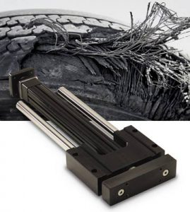
Challenge: Material reclamation from used tires for use in automotive tire manufacturing
Product Family: Electric
Product Used: GSA24 Guided Rod-Style Screw-Drive Electric Actuators

Challenge: Create a new generation mask-making machine based on the automated workcell concept to improve efficiency, quality and throughput.
Product Family: Electric
Product Used: B3W Rodless Actuators & GSA Guided Rod Actuators
Additional GSA information
GSA Linear Slide Actuators combine an electric rod actuator with guide rods, mounting blocks and bearings. A complete selection of sizes, options and system components are available. The GSA Linear Slide Actuator offers high performance, dependability and mounting flexibility for pivotal applications.
- 4 U.S. customary and metric body sizes
- Forces up to 4,160 lbf (18.5 kN)
- Wide tooling plate for end effector mounting
- Choice of linear ball or composite bearings with internal lubrication of guide rods for increased bearing life
- Standard or oversized guide rod diameter for increased rigidity and lower deflection
Stroke lengths up to 36 in (914 mm)