
 Ask an Engineer
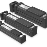
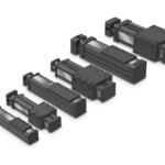
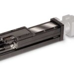
B3S Linear Actuators
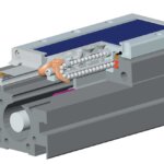
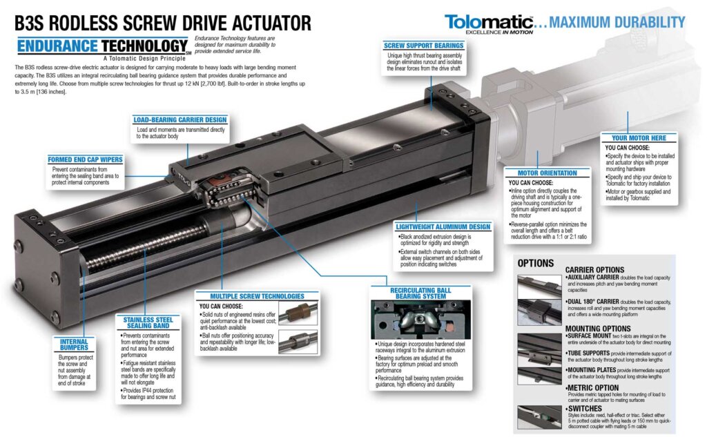
The B3S features a robust integrated and enclosed bearing design for the toughest environments
Tolomatic’s B3S is a linear screw driven rodless actuator series that has a enclosed carrier support bearing design that provides long life and high load capability. The bearings and screw are protected by a stainless steel dust band that provides a IP44 rating against dust and debris.
- 3 body sizes
- Maximum Load carrying capacity up to 8,032 lbf (3,642 kg)
- Stroke lengths up to 179 in (4.5m)
- Travel speeds up to 60 in/s (1.5 m/s)
- IP44 rating against dust and debris
- Auxiliary carrier and dual wraparound carrier options available for increased load capability
Features & Ordering
Download the B3S Brochure for full details on features
B3S Features
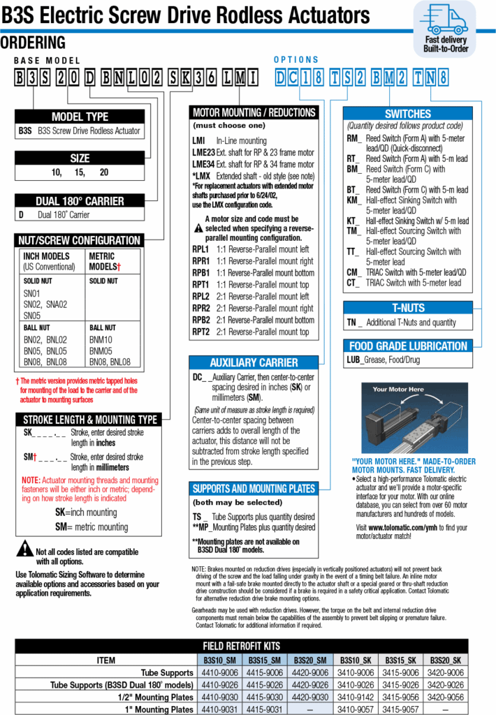
B3S Ordering
Specifications
| Specifications | Units | B3S10 | B3S15 | B3S20 |
|---|---|---|---|---|
| Maximum Stroke | in (mm) | 136 (3,454) | 133 (3,378) | 131 (3,337) |
| Maximum Force | lbf (N) | 170 (756) | 800 (3,559) | 2,700 (12,010) |
| Maximum Load | lbs (kg) | 591 (268) | 1,454 (660) | 2,008 (911) |
| Maximum Speed | in/sec (mm/sec) | 60 (1,524) | 60 (1,524) | 60 (1,524) |
B3S Screw Drive Specifications
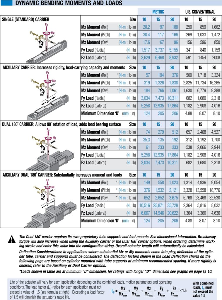
B3 Bending Moments - US Measurements
| Dynamic Bending Moments and Loads | U.S. CONVENTIONAL | ||||
|---|---|---|---|---|---|
| SINGLE (STANDARD) CARRIER | Size | 10 | 15 | 20 | |
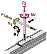 |
Mx Moment (Roll) | (lb-in) | 250 | 859 | 1,662 |
| My Moment (Pitch) | (lb-in) | 269 | 1,033 | 1,472 | |
| Mz Moment (Yaw) | (lb-in) | 156 | 596 | 850 | |
| Fy Load (Radial) | (lb) | 341 | 840 | 1,159 | |
| Fz Load (Lateral) | (lb) | 591 | 1454 | 2008 | |
| AUXILIARY CARRIER: Increases rigidity, load-carrying capacity and moments | Size | 10 | 15 | 20 | |
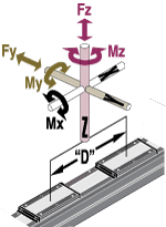 |
Mx Moment (Roll) | *(lb-in) | 500 | 1,718 | 3,324 |
| My Moment (Pitch) | *(lb-in) | 2,825 | 11,734 | 16,265 | |
| Mz Moment (Yaw) | *(lb-in) | 1,630 | 6,779 | 9,388 | |
| Fy Load (Radial) | (lb) | 682 | 1,680 | 2,318 | |
| Fz Load (Lateral) | (lb) | 1,182 | 2,908 | 4,016 | |
| Minimum Dimension ‘D’ ( in) | 4.88 | 8.07 | 8.10 | ||
| DUAL 180˚ CARRIER: Allows 90˚ rotation of load, adds load bearing surface | Size | 10 | 15 | 20 | |
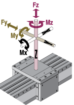 |
Mx Moment (Roll) | (lb-in) | 657 | 2,468 | 4,527 |
| My Moment (Pitch) | (lb-in) | 312 | 1,192 | 1,700 | |
| Mz Moment (Yaw) | (lb-in) | 538 | 2,066 | 2,944 | |
| Fy Load (Radial) | (lb) | 1,182 | 2,908 | 4,016 | |
| Fz Load (Lateral) | (lb) | 682 | 1,680 | 2,318 | |
| AUXILIARY DUAL 180˚ CARRIER: Substantially increases moment and loads | Size | 10 | 15 | 20 | |
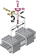 |
Mx Moment (Roll) | * (lb-in) | 1,314 | 4,936 | 9,054 |
| My Moment (Pitch) | * (lb-in) | 3,328 | 13,558 | 18,776 | |
| Mz Moment (Yaw) | * (lb-in) | 5,768 | 23,468 | 32,530 | |
| Fy Load (Radial) | (lb) | 2,364 | 5,816 | 8,032 | |
| Fz Load (Lateral) | (lb) | 1,364 | 3,360 | 4,636 | |
| Minimum Dimension ‘D’ ( in) | 4.88 | 8.07 | 8.10 | ||
The Dual 180˚ carrier requires its own proprietary tube supports and foot mounts. See dimensional information. Breakaway torque will also increase when using the Auxiliary carrier or the Dual 180˚ carrier options. When ordering, determine working stroke and enter this value into the configuration string. Overall actuator length will automatically be calculated.
Deflection Considerations: In applications where substantial Mx or My moments come into play, deflection of the cylinder tube, carrier and supports must be considered. The deflection factors shown in the Load Deflection charts on the following page are based on cylinder mounted with tube supports at minimum recommended spacing. If more rigidity is desired, refer to the Auxiliary or Dual Carrier options.
*Loads shown in table are at minimum “D” dimension, for ratings with longer “D” dimension see graphs in B3 Catalog 3600-4176
B3 Bending Moments - Metric Measurements
| Dynamic Bending Moments and Loads | METRIC | ||||
|---|---|---|---|---|---|
| SINGLE (STANDARD) CARRIER | Size | 10 | 15 | 20 | |
|
Mx Moment (Roll) | ( N-m ) | 28.2 | 97 | 188 |
| My Moment (Pitch) | ( N -m ) | 30.4 | 117 | 166 | |
| Mz Moment (Yaw) | ( N-m ) | 17.6 | 67 | 96 | |
| Fy Load (Radial) | ( kg ) | 155 | 381 | 526 | |
| Fz Load (Lateral) | ( kg ) | 268 | 660 | 911 | |
| AUXILIARY CARRIER: Increases rigidity, load-carrying capacity and moments | Size | 10 | 15 | 20 | |
|
Mx Moment (Roll) | *( N-m ) | 57 | 194 | 376 |
| My Moment (Pitch) | *( N-m ) | 319 | 1,326 | 1,838 | |
| Mz Moment (Yaw) | *( N-m ) | 184 | 766 | 1,061 | |
| Fy Load (Radial) | ( kg ) | 309 | 762 | 1,051 | |
| Fz Load (Lateral) | ( kg ) | 536 | 1,319 | 1,822 | |
| Minimum Dimension ‘D’ ( mm ) | 124 | 205 | 206 | ||
| DUAL 180˚ CARRIER: Allows 90˚ rotation of load, adds load bearing surface | Size | 10 | 15 | 20 | |
|
Mx Moment (Roll) | ( N-m ) | 74 | 279 | 512 |
| My Moment (Pitch) | ( N-m ) | 35.3 | 135 | 192 | |
| Mz Moment (Yaw) | ( N-m ) | 61 | 233 | 333 | |
| Fy Load (Radial) | ( kg ) | 536 | 1,319 | 1,822 | |
| Fz Load (Lateral) | ( kg ) | 309 | 762 | 1051 | |
| AUXILIARY DUAL 180˚ CARRIER: Substantially increases moment and loads | Size | 10 | 15 | 20 | |
|
Mx Moment (Roll) | * ( N-m ) | 149 | 558 | 1,023 |
| My Moment (Pitch) | * ( N-m ) | 376 | 1,532 | 2,121 | |
| Mz Moment (Yaw) | * ( N-m ) | 652 | 2,652 | 3,675 | |
| Fy Load (Radial) | ( kg ) | 1,072 | 2,638 | 3,643 | |
| Fz Load (Lateral) | ( kg ) | 619 | 1,524 | 2,103 | |
| Minimum Dimension ‘D’ ( mm ) | 124 | 205 | 206 | ||
The Dual 180˚ carrier requires its own proprietary tube supports and foot mounts. See dimensional information. Breakaway torque will also increase when using the Auxiliary carrier or the Dual 180˚ carrier options. When ordering, determine working stroke and enter this value into the configuration string. Overall actuator length will automatically be calculated.
Deflection Considerations: In applications where substantial Mx or My moments come into play, deflection of the cylinder tube, carrier and supports must be considered. The deflection factors shown in the Load Deflection charts on the following page are based on cylinder mounted with tube supports at minimum recommended spacing. If more rigidity is desired, refer to the Auxiliary or Dual Carrier options.
*Loads shown in table are at minimum “D” dimension, for ratings with longer “D” dimension see graphs in B3 Catalog 3600-4176
B3S Detailed Specifications - US Measurements
| B3S Size | Max Stroke | Screw Code | Screw Lead | Max Thrust* | Screw Dynamic Load Rating | Lead Accuracy | Backlash | Screw Diameter | Base Actuator Inertia | Base Actuator Inertia | Inertia Per in of Stroke | Maximum Dynamic Friction Torque |
|---|---|---|---|---|---|---|---|---|---|---|---|---|
| LMI | RP | |||||||||||
| in | in/rev | lbf | lbf | in/ft | in | in | lb-in2 | lb-in2 | lb-in2 | lb-in | ||
| 10 | 100.2 | SN01 | 1.000 | 170 | N/A | 0.0060 | 0.007 | 0.500 | 0.032 | 0.035 | 0.0017 | 2.5 |
| 134.2 | SN02 | 0.500 | 170 | N/A | 0.0050 | 0.007 | 0.500 | 0.016 | 0.019 | 0.0017 | 1.8 | |
| 134.2 | SNA02 | 0.500 | 170 | N/A | 0.0050 | 0.003 | 0.500 | 0.019 | 0.022 | 0.0017 | 1.8 | |
| 136.2 | SN05 | 0.200 | 170 | N/A | 0.0060 | 0.007 | 0.500 | 0.011 | 0.014 | 0.0017 | 1.3 | |
| 64.2 | BN08 | 0.125 | 151 | 300 | 0.0040 | 0.015 | 0.375 | 0.003 | 0.004 | 0.0005 | 1.1 | |
| 64.2 | BNL08 | 0.125 | 151 | 300 | 0.0040 | 0.002 | 0.375 | 0.003 | 0.004 | 0.0005 | 1.1 | |
| 64.2 | BNM10 | 0.394 | 414 | 562 | 0.0040 | 0.002 | 0.394 | 0.003 | 0.004 | 0.0009 | 1.2 | |
| 15 | 133.4 | SN01 | 1.000 | 300 | N/A | 0.0050 | 0.007 | 0.750 | 0.119 | 0.133 | 0.0087 | 2.8 |
| 133.4 | SN02 | 0.500 | 200 | N/A | 0.0050 | 0.007 | 0.625 | 0.048 | 0.055 | 0.0042 | 1.9 | |
| 133.4 | SNA02 | 0.500 | 200 | N/A | 0.0050 | 0.003 | 0.625 | 0.048 | 0.055 | 0.0042 | 1.9 | |
| 61.4 | BN02 | 0.500 | 855 | 1,071 | 0.0030 | 0.015 | 0.500 | 0.025 | 0.028 | 0.0017 | 1.6 | |
| 61.4 | BNL02 | 0.500 | 855 | 1,071 | 0.0030 | 0.002 | 0.500 | 0.025 | 0.028 | 0.0017 | 1.6 | |
| 61.4 | BN05 | 0.200 | 830 | 1,411 | 0.0030 | 0.015 | 0.625 | 0.040 | 0.047 | 0.0042 | 1.3 | |
| 61.4 | BNL05 | 0.200 | 830 | 1,411 | 0.0030 | 0.002 | 0.625 | 0.040 | 0.047 | 0.0042 | 1.3 | |
| 133.4 | BNM05 | 0.197 | 1,577 | 2,697 | 0.0019 | 0.002 | 0.630 | 0.041 | 0.048 | 0.0043 | 2.4 | |
| 20 | 131.4 | BN02 | 0.500 | 2,713 | 3,400 | 0.0040 | 0.015 | 0.750 | 0.116 | 0.122 | 0.0087 | 3.1 |
| 131.4 | BNL02 | 0.500 | 2,713 | 3,400 | 0.0040 | 0.002 | 0.750 | 0.116 | 0.122 | 0.0087 | 3.1 | |
| 131.4 | BN05 | 0.200 | 955 | 1,624 | 0.0030 | 0.015 | 0.750 | 0.105 | 0.111 | 0.0087 | 2.2 | |
| 131.4 | BNL05 | 0.200 | 955 | 1,624 | 0.0030 | 0.002 | 0.750 | 0.105 | 0.111 | 0.0087 | 2.2 | |
| 131.4 | BNM05 | 0.197 | 1,801 | 3,080 | 0.0019 | 0.003 | 0.787 | 0.110 | 0.117 | 0.0096 | 2.2 |
Contact Tolomatic for higher accuracy and lower backlash options.
*For Acme screws, maximum thrust is the maximum continuous dynamic thrust subject to Thrust x Velocity limitation.
For ball screws, maximum thrust reflects 90% reliability for 25 million linear millimeters of travel.
| Screw Code | Description | Efficiency |
|---|---|---|
| BN | Ball Nut | 0.9 |
| BNL | Low-Backlash Ball Nut | 0.9 |
| BNM | Ball Nut Metric | 0.9 |
| SN | Solid Nut | 0.6 |
| SNA | Anti-Backlash Solid Nut | 0.6 |
B3S Detailed Specifications - Metric Measurements
| B3S Size | Max Stroke | Screw Code | Screw Lead | Max Thrust | Screw Dynamic Load Rating | Lead Accuracy | Backlash | Screw Diameter | Base Actuator Inertia | Base Actuator Inertia | Inertia Per in of Stroke | Maximum Dynamic Friction Torque |
|---|---|---|---|---|---|---|---|---|---|---|---|---|
| LMI | RP | |||||||||||
| mm | mm/rev | N | N | mm/300mm | mm | mm | kg-cm 2 | kg-cm 2 | kg-cm 2 | N-m | ||
| 10 | 2,545.1 | SN01 | 25.40 | 756 | N/A | 0.15 | 0.1778 | 12.700 | 0.094 | 0.102 | 0.0002 | 0.28 |
| 3,408.7 | SN02 | 12.70 | 756 | N/A | 0.13 | 0.1778 | 12.700 | 0.047 | 0.056 | 0.0002 | 0.20 | |
| 3,408.7 | SNA02 | 12.70 | 756 | N/A | 0.13 | 0.0762 | 12.700 | 0.056 | 0.064 | 0.0002 | 0.20 | |
| 3,459.5 | SN05 | 5.08 | 756 | N/A | 0.15 | 0.1778 | 12.700 | 0.032 | 0.041 | 0.0002 | 0.15 | |
| 1,630.7 | BN08 | 3.18 | 671 | 1,334 | 0.10 | 0.3810 | 9.525 | 0.009 | 0.012 | 0.0001 | 0.12 | |
| 1,630.7 | BNL08 | 3.18 | 671 | 1,334 | 0.10 | 0.0508 | 9.525 | 0.009 | 0.012 | 0.0001 | 0.12 | |
| 1,630.7 | BNM10 | 10.00 | 1,842 | 2,500 | 0.10 | 0.0610 | 10.000 | 0.010 | 0.012 | 0.0001 | 0.13 | |
| 15 | 3,388.4 | SN01 | 25.40 | 1,334 | N/A | 0.13 | 0.1778 | 19.050 | 0.348 | 0.389 | 0.0010 | 0.32 |
| 3,388.4 | SN02 | 12.70 | 890 | N/A | 0.13 | 0.1778 | 15.875 | 0.140 | 0.161 | 0.0005 | 0.21 | |
| 3,388.4 | SNA02 | 12.70 | 890 | N/A | 0.13 | 0.0762 | 15.875 | 0.140 | 0.161 | 0.0005 | 0.21 | |
| 1,559.6 | BN02 | 12.70 | 3,801 | 4,764 | 0.08 | 0.3810 | 12.700 | 0.073 | 0.082 | 0.0002 | 0.18 | |
| 1,559.6 | BNL02 | 12.70 | 3,801 | 4,764 | 0.08 | 0.0508 | 12.700 | 0.073 | 0.082 | 0.0002 | 0.18 | |
| 1,559.6 | BN05 | 5.08 | 3,690 | 6,276 | 0.08 | 0.3810 | 15.875 | 0.117 | 0.138 | 0.0005 | 0.15 | |
| 1,559.6 | BNL05 | 5.08 | 3,690 | 6,276 | 0.08 | 0.0508 | 15.875 | 0.117 | 0.138 | 0.0005 | 0.15 | |
| 3,388.0 | BNM05 | 5.00 | 7,016 | 11,997 | 0.05 | 0.0508 | 16.000 | 0.120 | 0.140 | 0.0005 | 0.27 | |
| 20 | 3,337.6 | BN02 | 12.70 | 12,068 | 15,124 | 0.10 | 0.3810 | 19.050 | 0.339 | 0.357 | 0.0010 | 0.35 |
| 3,337.6 | BNL02 | 12.70 | 12,068 | 15,124 | 0.10 | 0.0508 | 19.050 | 0.339 | 0.357 | 0.0010 | 0.35 | |
| 3,337.6 | BN05 | 5.08 | 4,247 | 7,224 | 0.08 | 0.3810 | 19.050 | 0.307 | 0.325 | 0.0010 | 0.25 | |
| 3,337.6 | BNL05 | 5.08 | 4,247 | 7,224 | 0.08 | 0.0508 | 19.050 | 0.307 | 0.325 | 0.0010 | 0.25 | |
| 3,337.6 | BNM05 | 5.00 | 8,012 | 13,700 | 0.05 | 0.0700 | 20.000 | 0.322 | 0.342 | 0.0011 | 0.25 |
Contact Tolomatic for higher accuracy and lower backlash options.
*For Acme screws, maximum thrust is the maximum continuous dynamic thrust subject to Thrust x Velocity limitation.
For ball screws, maximum thrust reflects 90% reliability for 25 million linear millimeters of travel.
| Screw Code | Description | Efficiency |
|---|---|---|
| BN | Ball Nut | 0.9 |
| BNL | Low-Backlash Ball Nut | 0.9 |
| BNM | Ball Nut Metric | 0.9 |
| SN | Solid Nut | 0.6 |
| SNA | Anti-Backlash Solid Nut | 0.6 |
B3S Weights and Additional Specifications - US Measurements
| WEIGHT | WEIGHT PER UNIT OF STROKE | 1STRAIGHTNESS & FLATNESS (supported) | 2TEMPERATURE RANGE | 3IP RATING | ||
| CARRIER | BASE | |||||
| (lbs) | (lbs) | (lbs/in) | (in) | (°F) | ||
| B3S10 | 0.85 | 2.15 | 0.30 | 0.00067 x L* | 40 – 130 | 44 |
| B3S15 | 1.56 | 8.75 | 0.57 | |||
| B3S20 | 2.15 | 14.38 | 0.88 | |||
Dual 180 Carrier
| WEIGHT | WEIGHT PER UNIT OF STROKE | ||
|---|---|---|---|
| CARRIER | BASE | ||
| (lbs) | (lbs) | (lbs/in) | |
| B3S10D | 2.32 | 5.10 | 0.41 |
| B3S15D | 6.47 | 14.40 | 0.68 |
| B3S20D | 10.65 | 29.45 | 1.31 |
1The listed values relating to straightness/flatness are intended for reference purposes only, and not as an engineering standard of absolute tolerance for a given actuator. Appropriate installation is the single most important factor in reducing such deviation, so good engineering practices such as measurement, mapping, etc. must be employed in applications with stringent straightness/flatness requirements.
2Heat generated by the motor and drive should be taken into consideration as well as linear velocity and work cycle time. For applications that require operation outside of the recommended temperature range, contact the factory.
3Protected against ingress of solid particles greater than .039 in (1mm) and splashing water.
* “L” is maximum distance between supports— See the support recommendation graph in B3 Catalog 3600-4176.
LARGE FRAME MOTORS AND SMALLER SIZE ACTUATORS: Cantilevered motors need to be supported, if subjected to continuous rapid reversing duty and/or under dynamic conditions.
B3S Weights and Additional Specifications - Metric Measurements
| WEIGHT | WEIGHT PER UNIT OF STROKE | 1STRAIGHTNESS & FLATNESS (supported) | 2TEMPERATURE RANGE | 3IP RATING | ||
| CARRIER | BASE | |||||
| (kg) | (kg) | (g/mm) | (mm) | (°C) | ||
| B3S10 | 0.40 | 1.00 | 5.40 | 0.00067 x L* | 4 – 54 | 44 |
| B3S15 | 0.70 | 3.96 | 10.18 | |||
| B3S20 | 0.97 | 6.52 | 15.73 | |||
Dual 180 Carrier
| WEIGHT | WEIGHT PER UNIT OF STROKE | ||
|---|---|---|---|
| CARRIER | BASE | ||
| (lbs) | (lbs) | (lbs/in) | |
| B3S10D | 1.05 | 2.31 | 7.32 |
| B3S15D | 2.93 | 6.53 | 12.14 |
| B3S20D | 4.83 | 13.36 | 23.30 |
1The listed values relating to straightness/flatness are intended for reference purposes only, and not as an engineering standard of absolute tolerance for a given actuator. Appropriate installation is the single most important factor in reducing such deviation, so good engineering practices such as measurement, mapping, etc. must be employed in applications with stringent straightness/flatness requirements.
2Heat generated by the motor and drive should be taken into consideration as well as linear velocity and work cycle time. For applications that require operation outside of the recommended temperature range, contact the factory.
3Protected against ingress of solid particles greater than .039 in (1mm) and splashing water.
* “L” is maximum distance between supports— See the support recommendation graph in B3 Catalog 3600-4176.
LARGE FRAME MOTORS AND SMALLER SIZE ACTUATORS: Cantilevered motors need to be supported, if subjected to continuous rapid reversing duty and/or under dynamic conditions.
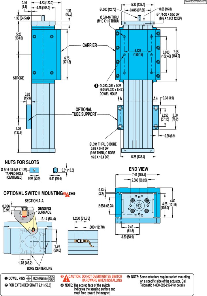
Dimensions
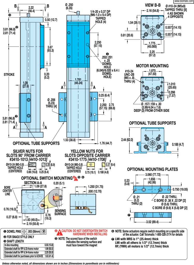
B3S10 Actuator & Options Dimensions
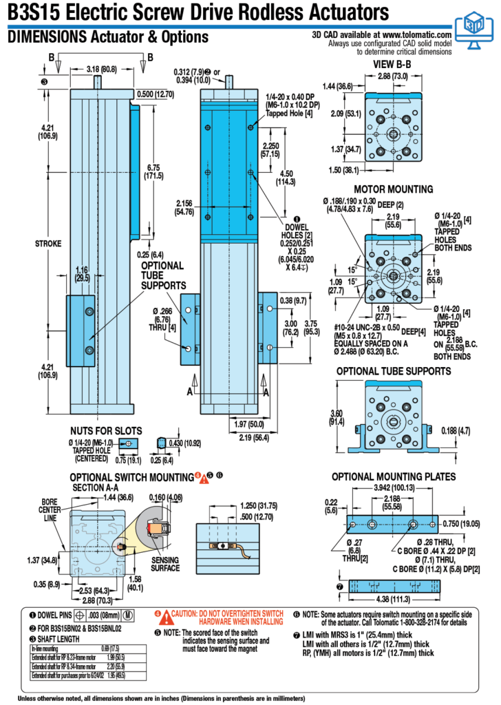
B3S15 Actuator & Options Dimensions
B3S20 Actuator & Options Dimensions

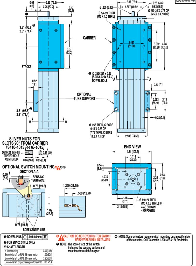
B3S10 Dual 180º Option Dimensions
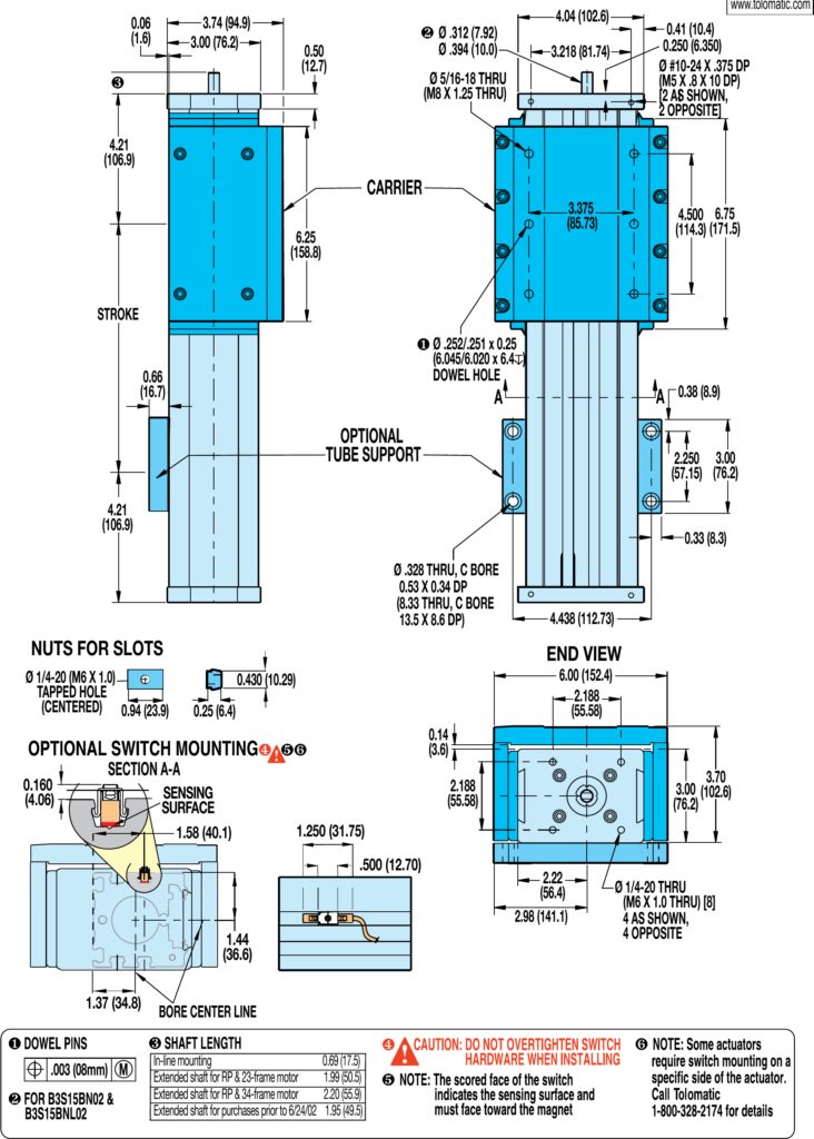
B3S15 Dual 180º Option Dimensions
B3S20 Dual 180º Option Dimensions
Get CAD
Manuals & Part Sheets
Additional Resources
Information Center:
Application Checklists
Case Studies
Catalogs & Brochures
- Corporate Overview-Linear Motion Solutions Brochure (English)
- SOLUCIONES DE CONTROL DE MOVIMIENTO (Spanish, Corporate Overview-Motion Control Solutions Brochure)
- Unternehmensübersicht (German, Corporate Overview brochure)
- Brochure sur l'entreprise Tolomatic (French, Corporate Overview-Linear Motion Solutions Brochure)
- B3S/B3W Electric Rodless Actuators Catalog
- Aplicaciounes de la Ind. Automotriz (Auto Appl SP)
- Gantry & Multi-Axis Solutions Brochure
- Soluciones Gantry y Multieje (^ES Gantry brochure)
- Medical and Life Sciences brochure
- OEM Actuator Solutions Brochure
Certifications
Guides
- Selecting the Optimal Screw Technology
- Actuator Life: How to estimate for ball and roller screw actuators
- INFOGRAPHIC: Accuracy and Repeatability in Linear Actuators
- INFOGRAPHIC: Ten Tips for Specifying Rodless Electric Linear Actuators
- INFOGRAPHIC: Calculating Total Cost of Ownership
- 如何选择 螺杆? 甄选 正确的技术 (Chinese, How to select the right lead screw for an electric actuator)
- Abschnitt: Welches Gewinde? Die richtige Technologie auswählen (German - Which Screw)
- Guide to Third Party Motor Integration
- Switch Reference Guide
Tech Bulletins
Terms & Conditions
White Papers
- Electric actuators vs. pneumatic cylinders: A comparison based on total cost of ownership
- The truth about actuator life: Screw drive survival
- Select the right linear actuator: Making sense of manufacturer specifications
- Specifying electric rodless actuators: Ten tips for maximizing actuator life and system performance
- Rules of actuator and guide alignment in linear motion systems
- IP ratings and the manufacturing environment: How to apply linear actuators for quality, safety and long service life.
- Minimizing electrical noise in actuator drive systems for maximum reliability and performance
- Screw-driven vs. belt-driven rodless actuators: How to select drive trains for reliability, efficiency and long service life
- Introduction to accuracy and repeatability in linear motion systems
- Elektrische Stangenantriebe vs. Hydraulikzylinder: Ein Vergleich der Vor- und Nachteile beider Technologien weißes Papier (Electric vs Hydraulic WP, German)
- Designing Gantry and Multi-Axis Automation Systems
Success Stories
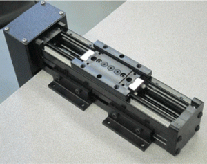
Product Family: Electric
Product Used: B3S Screw Drive Actuator
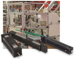
Application Description:
Convert the conveyor packer, located at the end of the conveyor, from pneumatic cylinders to electric actuators. Motions required include: several high-speed push operations, a centering operation, a tipping operation, and a container lift operation.