
 Ask an Engineer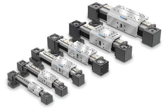

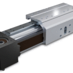
MXB-P Actuators
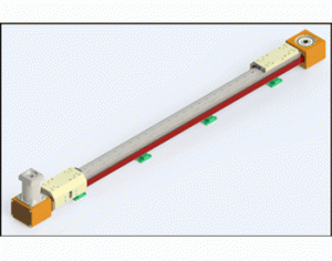
The MXB-P has a profiled rail that guides the carrier across the entire extrusion for high load capability.
The MXB is Tolomatic’s most advanced belt driven linear actuator series, with 3 different carrier guide options: Unguided (U), Solid Bearing (S), and Profiled Rail (P). The Profiled Rail carrier provides the highest load support and rigidity of the MXB series. The recirculating ball bearing linear guides allow for long operation life, easy maintenance, and high speed travel.
- 6 Body Sizes
- Maximum Load carrying capacity up to 2,583 lbf (1,171 kg)
- Stroke lengths up to 414 in (10.5m)
- Travel speeds up to 150 in/s (3.8 m/s)
- Acceleration capabilities up to 1200 in/sec^2 (30.5 mm/sec^2)
- Auxiliary carrier option for increased load and moment support
Features & Ordering
Download the MXB-P Brochure for full details on features
MXB-P Features
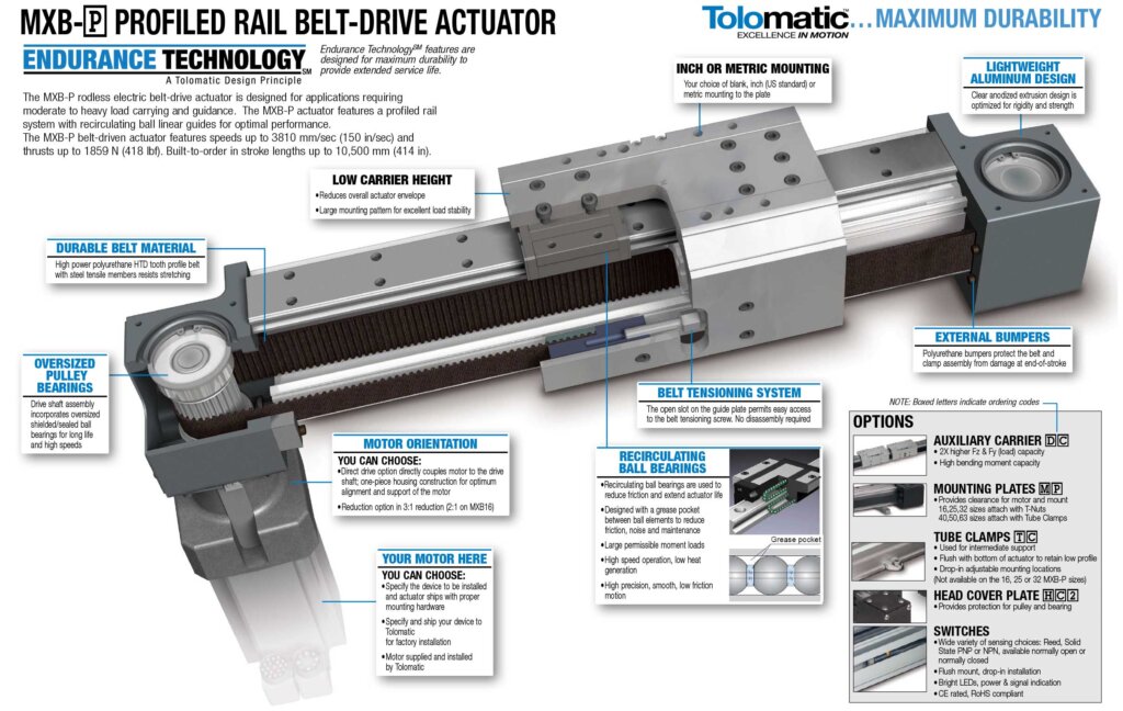
MXB-P Ordering

Specifications
| Specifications | Units | MXB16P | MXB25P | MXB32P | MXB40P | MXB50P | MXB63P |
|---|---|---|---|---|---|---|---|
| Maximum Stroke | in (mm) | 200 (5,080) | 414 (10,516) | 413 (10,490) | 412 (10,465) | 410 (10,414) | 217 (5,512) |
| Maximum Force | lbf (N) | 38 (169) | 151 (672) | 209 (930) | 250 (1,112) | 325 (1,446) | 418 (1,859) |
| Maximum Load | lbs (kg) | 217 (98) | 449 (204) | 569 (258) | 736 (334) | 1,014 (460) | 1,292 (586) |
| Maximum Speed | in/sec (mm/sec) | 150 (3,810) | 150 (3,810) | 150 (3,810) | 150 (3,810) | 150 (3,810) | 150 (3,810) |
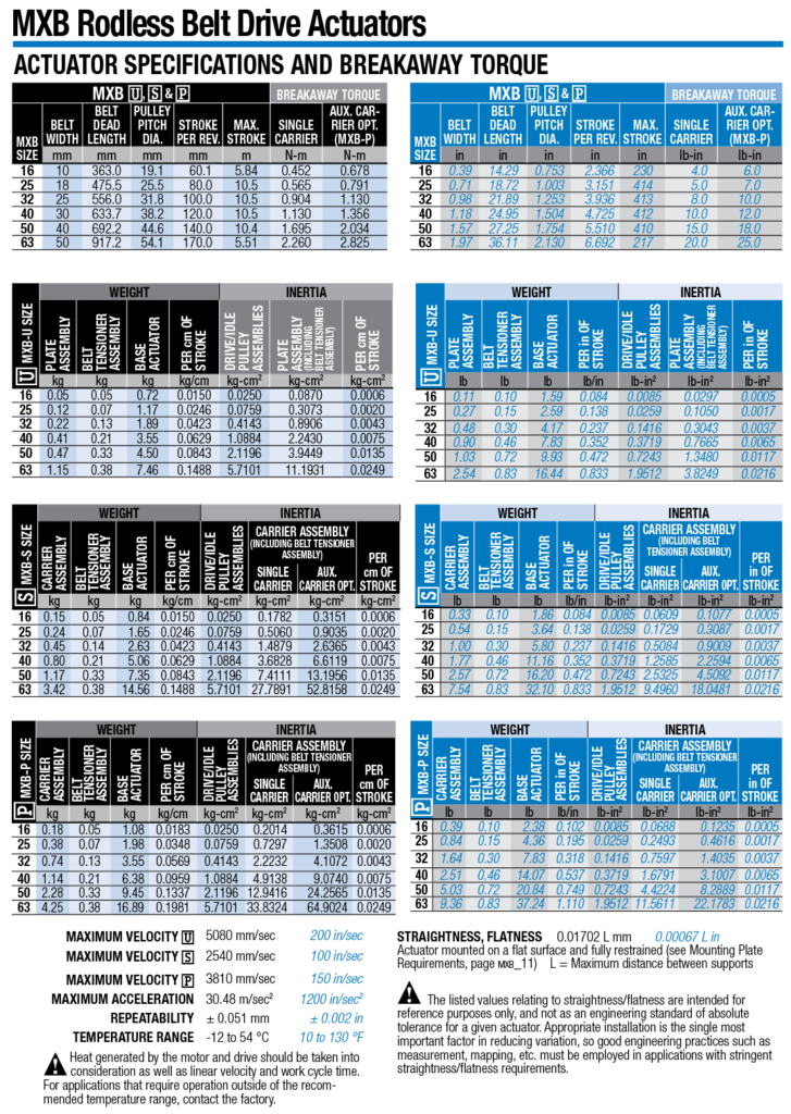
IMAGE-MXB-P Specifications and Breakaway Torque
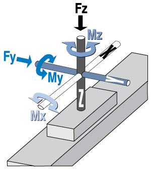
MXB-P Bending Moments and Load - US Measurements
|
 |
|||||||||||||||||||||||||||||||||||||||||||||||||||
MXB-P Bending Moments and Load - Metric Measurements
|
|
|||||||||||||||||||||||||||||||||||||||||||||||||||
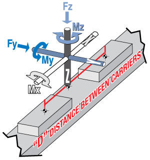
MXB-P Bending Moments and Load / Auxiliary Carrier - US Measurements
|
 |
|||||||||||||||||||||||||||||||||||||||||||||||||||
*At minimum “D” distance – see graph in MXB catalog 8500-4000 for bending moments at greater distances
MXB-P Bending Moments and Load / Auxiliary Carrier - Metric Measurements
|
|
|||||||||||||||||||||||||||||||||||||||||||||||||||
*At minimum “D” distance – see graph in MXB catalog 8500-4000 for bending moments at greater distances
MXB-P Detailed Specifications - US Measurements
| MXB-U, MXB-S, and MXB-P | BREAKAWAY TORQUE | ||||||
|---|---|---|---|---|---|---|---|
| MXB SIZE | Belt Width | Belt Dead Length | Pulley Pitch Dia. | Stroke per Rev. | Max. Stroke | Single Carrier | Aux. Carrier Opt. (MXB-P) |
| in | in | in | in | in | lb-in | lb-in | |
| 16 | 0.39 | 14.29 | 0.753 | 2.366 | 230 | 4.0 | 6.0 |
| 25 | 0.71 | 18.72 | 1.003 | 3.151 | 414 | 5.0 | 7.0 |
| 32 | 0.98 | 21.89 | 1.253 | 3.936 | 413 | 8.0 | 10.0 |
| 40 | 1.18 | 24.95 | 1.504 | 4.725 | 412 | 10.0 | 12.0 |
| 50 | 1.57 | 27.25 | 1.754 | 5.510 | 410 | 15.0 | 18.0 |
| 63 | 1.97 | 36.11 | 2.130 | 6.692 | 217 | 20.0 | 25.0 |
MXB-P Detailed Specifications - Metric Measurements
| MXB-U, MXB-S, and MXB-P | BREAKAWAY TORQUE | ||||||
|---|---|---|---|---|---|---|---|
| MXB Size | Belt Width | Belt Dead Length | Pulley Pitch Dia. | Stroke per Rev. | Max. Stroke | Single Carrier | Aux. Carrier Opt. (MXB-P) |
| mm | mm | mm | mm | m | N-m | N-m | |
| 16 | 10 | 363.0 | 19.1 | 60.1 | 5.84 | 0.452 | 0.678 |
| 25 | 18 | 475.5 | 25.5 | 80.0 | 10.5 | 0.565 | 0.791 |
| 32 | 25 | 556.0 | 31.8 | 100.0 | 10.5 | 0.904 | 1.130 |
| 40 | 30 | 633.7 | 38.2 | 120.0 | 10.5 | 1.130 | 1.356 |
| 50 | 40 | 692.2 | 44.6 | 140.0 | 10.4 | 1.695 | 2.034 |
| 63 | 50 | 917.2 | 54.1 | 170.0 | 5.51 | 2.260 | 2.825 |
MXB-P Weight, Inertia - US Measurements
| MXB-P SIZE | WEIGHT | INERTIA | ||||||
|---|---|---|---|---|---|---|---|---|
| Carrier Assembly | Belt Tensioning Assembly | Base Actuator | Per in of Stroke | Drive/Idle Pulley Assemblies | Carrier Assembly (Including Belt Tensioner Assembly) | Per in of Stroke | ||
| Single Carrier | Aux. Carrier Opt. | |||||||
| lb | lb | lb | lb/in | lb-in2 | lb-in2 | lb-in2 | lb-in2 | |
| 16 | 0.39 | 0.10 | 2.38 | 0.102 | 0.0085 | 0.0688 | 0.1235 | 0.0005 |
| 25 | 0.84 | 0.15 | 4.36 | 0.195 | 0.0259 | 0.2493 | 0.4616 | 0.0017 |
| 32 | 1.64 | 0.30 | 7.83 | 0.318 | 0.1416 | 0.7597 | 1.4035 | 0.0037 |
| 40 | 2.51 | 0.46 | 14.07 | 0.537 | 0.3719 | 1.6791 | 3.1007 | 0.0065 |
| 50 | 5.03 | 0.72 | 20.84 | 0.749 | 0.7243 | 4.4224 | 8.2889 | 0.0117 |
| 63 | 9.36 | 0.83 | 37.24 | 1.110 | 1.9512 | 11.5611 | 22.1783 | 0.0216 |
MXB-P Weight, Inertia - Metric Measurements
| MXB-P Size |
Weight | Inertia | ||||||
|---|---|---|---|---|---|---|---|---|
| Carrier Assembly | Belt Tensioning Assembly | Base Actuator | Per cm of Stroke | Drive/Idle Pulley Assemblies | Carrier Assembly (Including Belt Tensioner Assembly) | Per cm of Stroke | ||
| Single Carrier | Aux. Carrier Opt. | |||||||
| kg | kg | kg | kg/cm | kg-cm2 | kg-cm2 | kg-cm2 | kg-cm2 | |
| 16 | 0.18 | 0.05 | 1.08 | 0.0183 | 0.0250 | 0.2014 | 0.3615 | 0.0006 |
| 25 | 0.38 | 0.07 | 1.98 | 0.0348 | 0.0759 | 0.7297 | 1.3508 | 0.0020 |
| 32 | 0.74 | 0.13 | 3.55 | 0.0569 | 0.4143 | 2.2232 | 4.1072 | 0.0043 |
| 40 | 1.14 | 0.21 | 6.38 | 0.0959 | 1.0884 | 4.9138 | 9.0740 | 0.0075 |
| 50 | 2.28 | 0.33 | 9.45 | 0.1337 | 2.1196 | 12.9416 | 24.2565 | 0.0135 |
| 63 | 4.25 | 0.38 | 16.89 | 0.1981 | 5.7101 | 33.8324 | 64.9024 | 0.0249 |
MXB-P Max. Velocity, Acceleration, Temp. Range
| MAXIMUM VELOCITY MXB-P | 3,810 mm/sec | 150 in/sec |
| MAXIMUM ACCELERATION | 30.48 m/sec 2 | 1,200 in/sec 2 |
| REPEATABILITY | ± 0.051 mm | ± 0.002 in |
| TEMPERATURE RANGE | -12 to 54 °C | 10 to 130 °F |
| Heat generated by the motor and drive should be taken into consideration as well as linear velocity and work cycle time. For applications that require operation outside of the recommended temperature range, contact Tolomatic. | ||
STRAIGHTNESS, FLATNESS 0.01702 L mm 0.00067 L in
Actuator mounted on a flat surface and fully restrained (see Mounting Plate Requirements, MXB catalog 8500-4000 page mxb_11)
L = Maximum distance between supports
The listed values relating to straightness/flatness are intended for reference purposes only, and not as an engineering standard of absolute tolerance for a given actuator. Appropriate installation is the single most important factor in reducing variation, so good engineering practices such as measurement, mapping, etc. must be employed in applications with stringent straightness/flatness requirements.
Dimensions
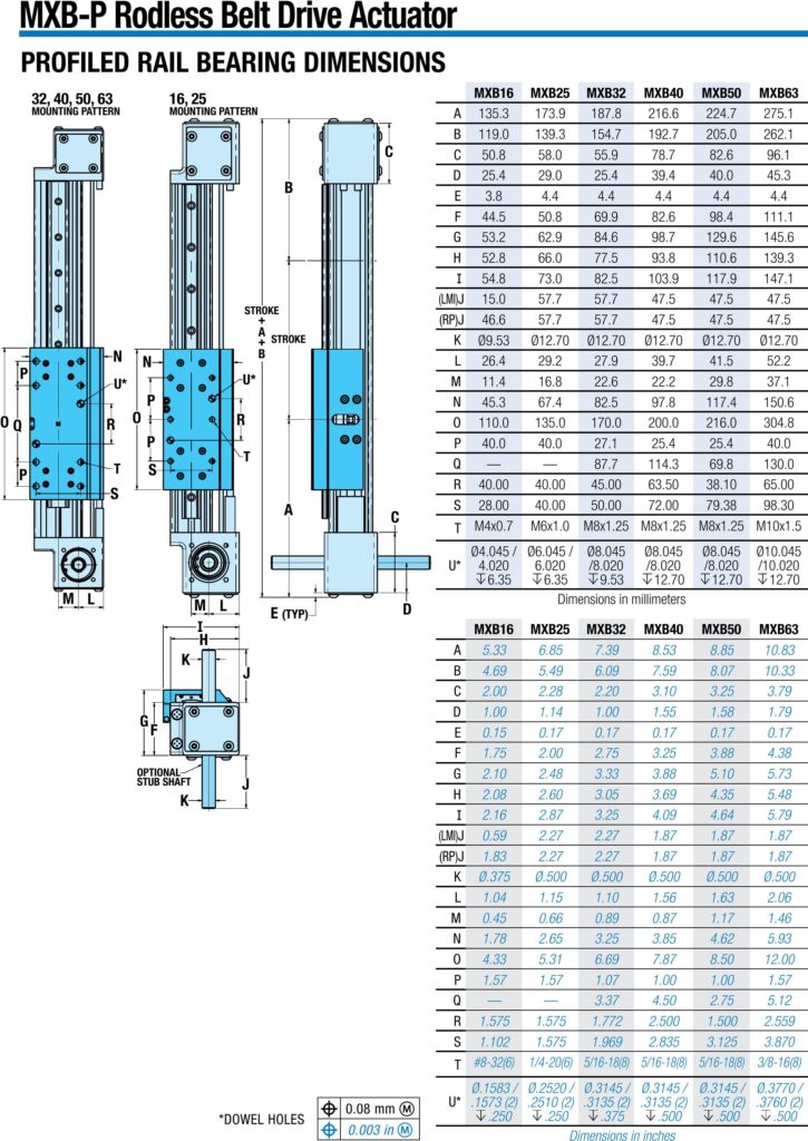
MXB-P Actuator Dimensions
Get CAD
Manuals & Part Sheets
- MXB16P Profiled Rail, Belt-Drive Actuators Part Sheet
- MXB25P Profiled Rail, Belt-Drive Actuators Part Sheet
- MXB32P Profiled Rail, Belt-Drive Actuators Part Sheet
- MXB40P Profiled Rail, Belt-Drive Actuators Part Sheet
- MXB50P Profiled Rail, Belt-Drive Actuators Part Sheet
- MXB63P Profiled Rail, Belt-Drive Actuators Part Sheet
Additional Resources
Information Center:
Application Checklists
Case Studies
Catalogs & Brochures
- Corporate Overview-Linear Motion Solutions Brochure (English)
- SOLUCIONES DE CONTROL DE MOVIMIENTO (Spanish, Corporate Overview-Motion Control Solutions Brochure)
- Unternehmensübersicht (German, Corporate Overview brochure)
- Brochure sur l'entreprise Tolomatic (French, Corporate Overview-Linear Motion Solutions Brochure)
- MXB Belt-Driven Linear Actuator Product Catalog
- Aplicaciounes de la Ind. Automotriz (Auto Appl SP)
- Gantry & Multi-Axis Solutions Brochure
- Soluciones Gantry y Multieje (^ES Gantry brochure)
- OEM Actuator Solutions Brochure
Certifications
E-Books
Tech Bulletins
Terms & Conditions
Videos
White Papers
- Electric actuators vs. pneumatic cylinders: A comparison based on total cost of ownership
- Select the right linear actuator: Making sense of manufacturer specifications
- Specifying electric rodless actuators: Ten tips for maximizing actuator life and system performance
- Rules of actuator and guide alignment in linear motion systems
- IP ratings and the manufacturing environment: How to apply linear actuators for quality, safety and long service life.
- Minimizing electrical noise in actuator drive systems for maximum reliability and performance
- Screw-driven vs. belt-driven rodless actuators: How to select drive trains for reliability, efficiency and long service life
- Introduction to accuracy and repeatability in linear motion systems
- Elektrische Stangenantriebe vs. Hydraulikzylinder: Ein Vergleich der Vor- und Nachteile beider Technologien weißes Papier (Electric vs Hydraulic WP, German)
- Elektrische Antriebe und Pneumatikzylinder: Ein Vergleich basierend auf den Gesamtbetriebskosten weißes Papier (GERMAN, TCO WhitePaper)
- Designing Gantry and Multi-Axis Automation Systems
Success Stories
Product Family: Electric
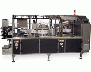
Product Used: 2 MXB-P rodless belt drive actuators
Product Family: Electric
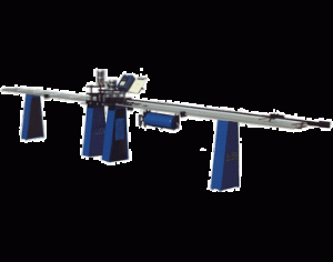
Product Used: MXB
Product Family: Electric
Product Used: MXB-P
Product Family: Electric
Product Used: MXB Belt Drive Actuator
Product Family: Electric
Product Used: MXB belt drive actuator
Product Family: Electric
Product Used: MXB40P
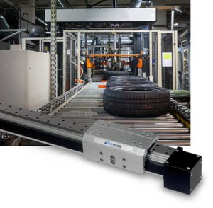
Challenge: Indexing tires for verification by a camera system during the manufacturing process.
Product Family: Electric
Product Used: MXB63P Profiled Rail, Belt-Drive Electric Rodless Actuator
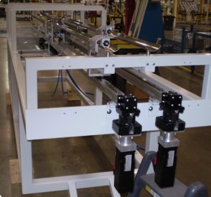
Challenge: Pick and place can lid transfer for handling and packaging equipment
Product Family: Electric
Product Used: MXB, JVL